Adjustable wrench
Crosstip screwdriver
5/16 IN. Socket or Nut-driver
Wire cutters
Kit number
14919
14937
Estimated Time
1 Hour
-
Remove the front control panel.
-
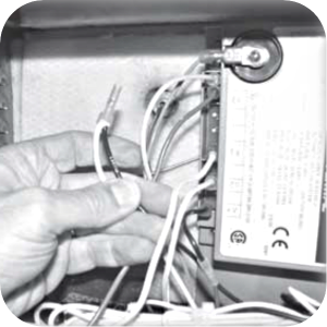
For Electromechanical fryers locate wires PV/MV and TR/G from the module. Cut and strip the ends of these wires and crimp them together onto a female terminal, provided in the kit.
-
Locate the "SENSE" wire (wired from the module to the flame sensor) and remove wire from unit.
-
Label and remove the rest of the wires from module.
-
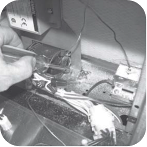
Use 5/16 in. socket or nut-driver to remove the nuts and screws securing the module bracket.
-
Remove bracket and module from unit.
-
Locate new bracket and module in kit and screw the module onto the bracket, use screws provided in the kit.
-
Fasten the bracket assembly into fryer, use previous hardware.
-
Locate "SEN" (SENSE) wire assembly in kit and connect one end of the wire to flame sensor and run the other end to the control panel area and connect to terminal SENSE on module.
-
Connect the rest of the wires to the module.
-
Computron fryers do not have a PV/MV wire so connect the TR/G wire to PV/MV terminal on the fenwall module.
-
Check cooling fan for obstructions before installing control panel and ensure fan is functioning.
-
Replace control panel and restore power to fryer.

|
To avoid electrical shock or property damage, move the power switch to OFF and disconnect power. |
Related Content
Replacing the High Temperature Limit Control
Checking the Temperature Probe Calibration for Chick-fil-A
Replacing the Temperature Probe
Calibrating The Standard Single Stage Thermostat
Replacing the Gas Burner Assembly
Replacing the Main Power Switch
PFG 600 SSI Fryers Gas Valve Replacement Kit
Direct connect retrofit PFG 600
Direct connect retrofit PFG-600
Temperature Probe Gauge Instructions
Troubleshooting E-1 Frypot Protection System (FPS)
Troubleshooting the PFG 600 E-12 FPS Probe Failure Error Code
Troubleshooting Oil Melting or Heating Slowly
Troubleshooting the PFG 600 E-20C No PV Error Code
Troubleshooting the PFG 600 E-20D Ignition Failure Error Code
Troubleshooting the PFG 600 E-92 24V Fuse Error Code
Direct connect oil system operating instructions
Electronic C2000 Simple Control Retrofit Kit
Installation of PFG 600 and PFG 600 SSI FM07-366 Electromechanical to C1000 Retrofit
PFG 600 SSI Electronic C1000 to C8000 Retrofit Kit
4 Head PFE 500/ PFG 600 Removing the Lid
RLink programming instructions
Pressure Assist Kit Installation
PFE 500/PFG 600 Wi-Fi Verification and Troubleshooting Instructions
PFE 500/PFG 600 Hybrid Control Installation Instructions
2nd Generation Radio for SMS: Hardware Installation
2nd Generation Radio for SMS: Software Update
FM08-748 2nd Generation Radio for SMS: Troubleshooting
Instructions for Fryer Control Replacement Kits
SMS 20 Auto Polish Programming Instructions
SAE Thread Filter Pump Installation
Pre VA SAE Thread Filter Pump Installation
Hybrid Control and Wi-Fi Installation
Reference