Adjustable wrench
Pipe sealant
Crosstip screwdriver
Kit number
14366
Estimated Time
30 minutes to 1 hour
-
Note before starting, This system is designed to operate using only a 1/2 hp pump motor. If the motor data plate reads 1/3 hp then replace with a 1/2 hp pump motor.
Note:It is recommended to use pipe sealant for all threaded joints.
-
Disconnect power to fryer and allow fryer to cool.
-
Remove the oil discard pipe and remove the quick disconnect receptacle from the pipe. Save the pipe for reuse. Discard the quick disconnect receptacle.
-
Remove the 3/8 in. 90° fitting and the nipple connecting it to the "tee" fitting.
-
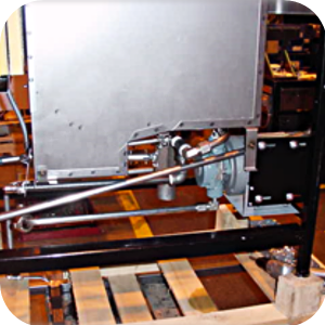
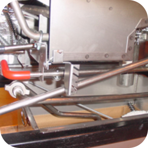
Install the valve assembly to the "tee" fitting and orient the valve assembly.
-
Install the 11 1/2 nipple to the valve assembly.
-
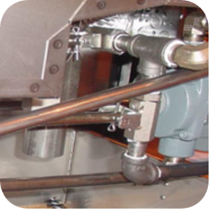
Screw the bushing on the nipple then screw the elbow onto the bushing.
-
Screw the hose assembly onto the end of the elbow.
-
Use screws from the kit to screw the spring bracket onto the handle bracket.
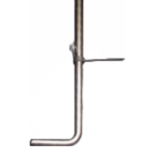
-
Slide through the existing bracket hole and install the red sleeve.
-
Attach the end of the new handle to the valve assembly by inserting the cotter pin into the holes on the handle and the valve.
-
Bend the ends of the cotter pin to the handle to the valve.
-
Test the red handle and verify the spring allows the valve to open completely by hand and close completely. Adjust the tension of the spring by placing the end of the spring into a different slot on the bracket.
-
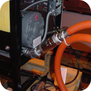
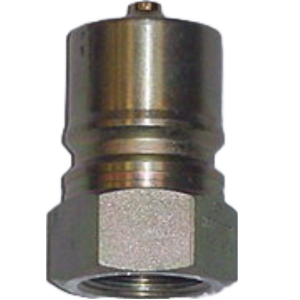
Install the male quick-disconnect to the manifold attached to the wall behind the fryer.
-
Connect the female end to the male end of the quick-disconnect.
Related Content
Replacing the High Temperature Limit Control
Checking the Temperature Probe Calibration for Chick-fil-A
Replacing the Temperature Probe
Calibrating The Standard Single Stage Thermostat
Replacing the Gas Burner Assembly
Replacing the Main Power Switch
PFG 600 SSI Fryers Gas Valve Replacement Kit
Direct connect retrofit PFG-600
PFG 600 Ignition Module Retrofit Kit
Temperature Probe Gauge Instructions
Troubleshooting E-1 Frypot Protection System (FPS)
Troubleshooting the PFG 600 E-12 FPS Probe Failure Error Code
Troubleshooting Oil Melting or Heating Slowly
Troubleshooting the PFG 600 E-20C No PV Error Code
Troubleshooting the PFG 600 E-20D Ignition Failure Error Code
Troubleshooting the PFG 600 E-92 24V Fuse Error Code
Direct connect oil system operating instructions
Electronic C2000 Simple Control Retrofit Kit
Installation of PFG 600 and PFG 600 SSI FM07-366 Electromechanical to C1000 Retrofit
PFG 600 SSI Electronic C1000 to C8000 Retrofit Kit
4 Head PFE 500/ PFG 600 Removing the Lid
RLink programming instructions
Pressure Assist Kit Installation
PFE 500/PFG 600 Wi-Fi Verification and Troubleshooting Instructions
PFE 500/PFG 600 Hybrid Control Installation Instructions
2nd Generation Radio for SMS: Hardware Installation
2nd Generation Radio for SMS: Software Update
FM08-748 2nd Generation Radio for SMS: Troubleshooting
Instructions for Fryer Control Replacement Kits
SMS 20 Auto Polish Programming Instructions
SAE Thread Filter Pump Installation
Pre VA SAE Thread Filter Pump Installation
Hybrid Control and Wi-Fi Installation
Reference