Applies to:

Replacing High Limit Probe
 Required tools
-
1/2 in (13 mm) Crowfoot or wrench
-
3/8 in (10 mm) Socket or wrench
-
5/16 in (8 mm) Socket or wrench
-
Rachet driver and extension
-
Crosstip screwdriver
-
Short flat head screwdriver
-
Wire cutters
Kit contents
-
High Limit Probe
-
Wire Ties
Kit number
140986 - High Limit Probe Replacement Kit Full Vat
140987 - High Limit Probe Replacement Kit Split Vat
Estimated Time
45 minutes

|
Only perform this procedure when the fryer is cool or severe burns may result. |
Preparing Fryer
-
Verify the drain pan is empty, assembled properly, and inserted under the fryer.
-
Access the filter menu and drain oil from the vat to the pan by selecting Settings > Oil & Filter > Drain to Pan.
NOTE: If you are on a split vat, select the side that needs to be empty.
-
Turn power switch off.
-
Ensure fryer is cool to the touch before moving.
-
Pull out the fryer and unplug from power source.
Removing High Limit Probe
-
Using a crosstip screwdriver, remove the screw securing the display control and carefully lower.
-
Disconnect the High Limit Probe, Temperature Probe, and Level Probe connections.
-
Temperature Probe: Red wires
-
Left Level Probe: Blue wires
-
Right Level Probe: White wires
-
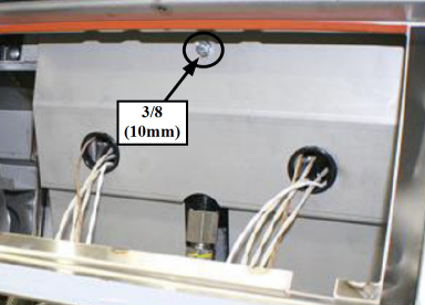
Remove the nut holding the upper heat shroud using a 3/8 in (10 mm) socket.
-
Remove the heat shroud and set aside.
-
Carefully remove any zip ties attached to the probe harnesses.
-
Using a 5/16 in (8 mm) socket, loosen the right and left side screws holding the lower heat shields.
-
Pull the shield sides off and push down to release the lower shield. This can also be removed completely.
-
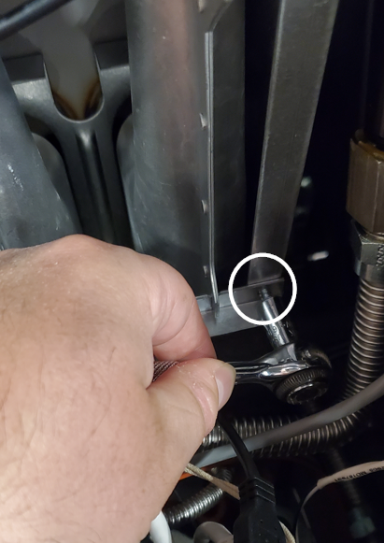
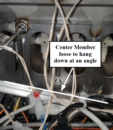
Using a 5/16 in (8 mm) socket, remove the right screw from the center member of the burner assembly.
-
Loosen the left side screw of the center member to allow enough slack to pull down.
-
Remove the burner tubes to access the High Limit Probe.
-
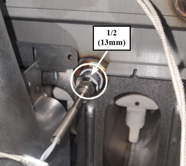
Using a 1/2 in (13 mm) crowfoot or wrench, loosen the bushing and remove probe from the vat.
RECOMMENDATION: Rather than accessing and replacing probes with control still in place, we recommend carefully disconnecting all the harnesses and ground wire from the control and set control off to the side.
NOTE: For reference, take a picture of the connections prior to disconnecting. A 3/8 in (10 mm) socket is needed for grounding nut.
Before proceeding, it may be easier to remove the mid-shelf cover to access the GMU area better. This also provides more room to work on the burner assembly.
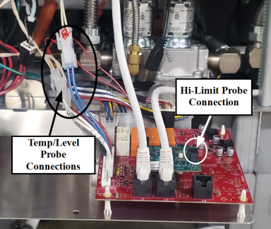
NOTE: High Limit Probe is connected to the High Limit board on the GMU.
Probe Harness Color Code:
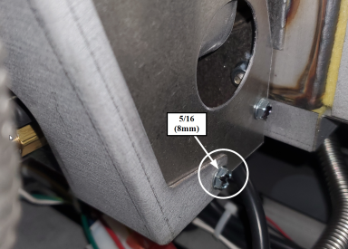
NOTE: These only need loosened and may require the mid-shelf panel to be lowered to gain better access.
Installing High Limit Probe
-
Install the new High Limit Probe into the vat and into the barbell fitting using food safe high temperature thread sealant and tighten bushing using 1/2 in (13 mm) crowfoot or wrench.
-
Adjust the probe to run parallel with the burner tube and hand tighten the compression nut to snug. Then, using a 3/8 in (10 mm) wrench turn another 3/4 turn to secure the probe in place.
-
Replace burner tubes from left to right making sure they are lining up correctly on the notches of the center member and manifold orifices at the top. Then, screw in right cross member but leave loose.
-
Replace lower heat shield and mate the top of it to the bottom of the center member. Tighten screws of lower heat shroud. Tighten center member screws using a 5/16 in (8 mm) socket.
-
Working in reverse, complete step 4 in Removing High Limit Probe section through step 1 in Preparing Fryer section. Then, return fryer to operation.
IMPORTANT: Do not fully tighten compression nut!
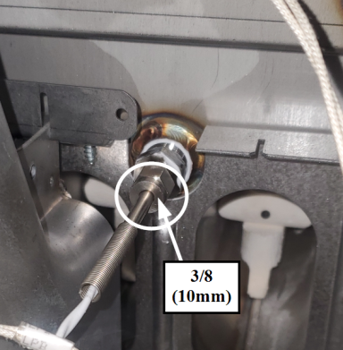
IMPORTANT: Do not overtighten. This can cause the ferrule to crimp the probe and damage it.
Related Content
Troubleshooting an E-4 Error VIU/OMS/GMU Board Overheating
Troubleshooting an E-5 Oil Too Hot Error Code
Troubleshooting an E-6 (A-B) Temperature Probe Failed Error Code
Troubleshooting an E-10 High Limit Error Code
Troubleshooting the E-20 (A-B) Pressure Switch Stuck Closed/Open Error Code
Troubleshooting the E-20 C Pilot Valve Signal Not Detected Error Code
Troubleshooting the E-20 D Gas Ignition Failure No MV Signal Error Code
Troubleshooting the E-20 (J-K) PV2/MV2 Jumper Missing (Split Vat Only) Error Code
Troubleshooting the E-20 M GMU Relay Failure (MV) Error Code
Troubleshooting the E-20 S Safety Relay Failure Error Code
Troubleshooting an E-21 Slow Heat Recovery Error Code
Troubleshooting an E-22 No Heat Error Code
Troubleshooting the E-93T Transformer 24 VAC Failure/Not Connected Error Code
Replacing Temperature and Level Probe
Replacing Blower Control Board
Troubleshooting an E-4 Error VIU/OMS/GMU Board Overheating
Troubleshooting an E-5 Oil Too Hot Error Code
Troubleshooting an E-6 (A-B) Temperature Probe Failed Error Code
Troubleshooting an E-10 High Limit Error Code
Troubleshooting the E-20 (A-B) Pressure Switch Stuck Closed/Open Error Code
Troubleshooting the E-20 C Pilot Valve Signal Not Detected Error Code
Troubleshooting the E-20 D Gas Ignition Failure No MV Signal Error Code
Troubleshooting the E-20 (J-K) PV2/MV2 Jumper Missing (Split Vat Only) Error Code
Troubleshooting the E-20 M GMU Relay Failure (MV) Error Code
Troubleshooting the E-20 S Safety Relay Failure Error Code
Troubleshooting an E-22 No Heat Error Code
Troubleshooting the E-21 Slow Heat Recovery Error Code
Troubleshooting the E-93T Transformer 24 VAC Failure/Not Connected Error Code
Reference