Testing the Relay and Replacing the Drive Motor
9/16" socket
drive motor
Kit number
14242
Estimated Time
1 Hour
Testing the Relay

|
SHOCK HAZARD To avoid electrical shock, perform relay checks or transformer checks as described as instructions. |
The following checks are performed with the wall circuit breaker closed and the main power switch in the ON position. Extreme caution should be taken. Make connections before applying power, take reading, and remove power before removing meter leads, or electrical shock could result.
A drive motor may not be running due to a defective relay.
The rotation switch bypasses the relay allowing power to go directly to the drive motor.
-
Use the rotation switch to test the relay.
-
There should be DC input voltage and the AC contact should be closed.
-
If the relay is defective, replace it.
Replacing the Drive Motor
|
|
To avoid electrical shock or property damage, disconnect power before installing or servicing equipment. A qualified technician must perform the service procedures. |
-
Remove electrical power to unit.
-
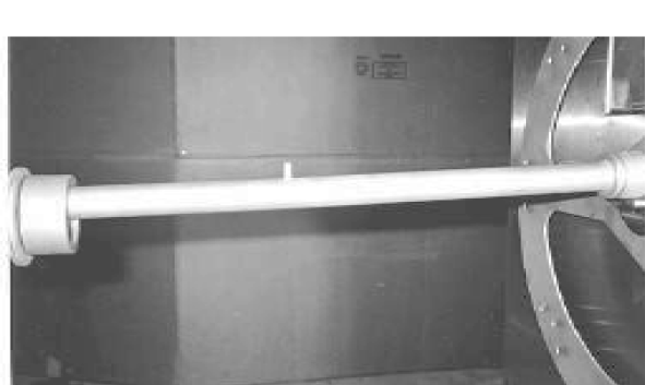
Remove rod and discs from unit.
-
From the control side of the unit, remove the right side panel.
-
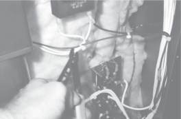
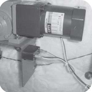
Cut the three wires from the motor.
-
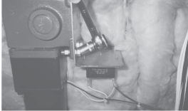
Use a 9/16" socket, remove the bolts securing the motor to the bracket, and pull motor from unit.
-
Slide extension hub (on motor) into slot on the unit, and bolt the motor to the bracket.
-
Snug, but don’t tighten nuts.
-
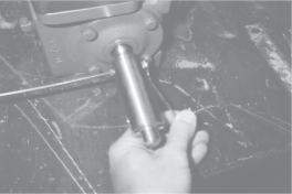
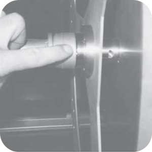
Install discs into unit and place rod into place.
NOTICE -
When removing the rod assembly, make sure indicator is pointed up towards top of unit. If it is pointed down, the rod assembly will fall and may be damaged.
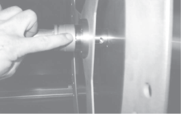
The gap between the end of the rod and the disc hub should not be more than 1/16" (1.6 mm) or damage to rod and disc assembly could occur.
-
Adjust motor on bracket so no more than 1/16" (1.6 mm) gap is present and the end of the rod is even all around hub.
-
Once rod is lined up, tighten nuts on bracket.
-
Splice wires of motor onto the cut wires, according to colors.
-
Remove wires to the drive motor capacitor, mounted under the motor.
-
Remove the capacitor from the unit and replace with the one in the kit.
-
Replace side panel and restore power.
Related Content
Replacing the Drive Motor Capacitor
Replacing the Meat Probe Receptacle
Installing the Rotation Switch
SCR Stacking Kit Instructions Short
Rotisserie Stacking Instructions
Troubleshooting a Broken Shaft Adapter Pin
Radiant Heat Deflectors Instructions
Radiant Heat Deflectors Instructions
SCR 6/8 Lamp Guard Installation Instructions
Reference