Applies to:
![]()
ALL CUSTOMERS
PFE 590 and 591 Electronic Control Retrofit Computron 7000 to New Electronic Controls
5/16 in. Nut driver
1/4 in. Straight blade screwdriver
Crosstip head screwdriver
Needle nose pliers
Wire strippers/crimpers
Kit number
14455
14456
14786
14787
Estimated Time
1.5 to 2 Hours

|
To avoid electrical shock or property damage, move the power switch to OFF and disconnect power. |
-
Installation should be preformed only by a qualified service technician.
-
Disconnect power from unit.
-
Remove 2 screws from the control panel.
-
Lift panel up and out.
-
Unplug the 9-pin connector and the probe connection at the control board.
-
Remove control from unit.
-
Remove 2 screws from the right side panel and pull side panel from unit.
-
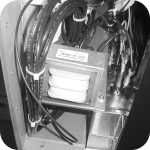
Remove the retaining clip from the top of the solenoid (Remove screw if necessary) coil housing and remove the cover.
-
Pull the coil housing from solenoid.
-
Remove the coil from the housing and replace with the low voltage coil supplied in the kit. Ensure to replace the spacers from the old coil onto the new coil.
-
Label remove and element wires from both the mercury and standard contactors.
-
Pull wires from contactor coils and discard.
-
Remove or cut remaining wires to 9-pin connector and remove 9-pin connector from unit.
-
Install the low voltage mercury and standard CONTROLS AND contactors, provided in the kit. Ensure the arrow on COMPONENTS mercury contactor is pointed in the proper direction.
-
Connect wires to the contactors, making sure the element wires are placed in the proper locations.
-
Use a crosstip head screwdriver to remove the 2 screws from the left side panel and pull side panel from unit.
-
Install transformer provided in the kit to the control area. Use stud and nut already in place.
-
Locate and cut the wires to the filter switch and high limit about 10 inches from the component.
-
Discard any other wires in wire nuts.
-
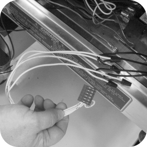
Locate the wire harness with the 6-pin red connector.
-
Connect the yellow wires to the high limit wires usng wire nuts. If too long, cut to appropriate length.
-
Connect the white wires to the filter switch wires using wire nuts.
-
-
Install spade terminals onto the pressure solenoid wires if crimpers are available. If not, leave as is and use wire nuts in the next step.
-
Locate the wire harness with the 12 pin red connector.
-
Connect the pressure solenoid wires to the red wires in positions 1 & 2 of the 12 pin connector.
-
Connect the yellow wires in position 6 & 7 of the 12-pin connector to the coil of the Primary (right) Contactor.
-
Connect the blue wires in positions 11 & 12 of the 12 pin connector to the coil of Secondary (left) Contactor.
-
-
Next step depends on the voltage of the fryer.
-
For 208-240 Volt fryers:
-
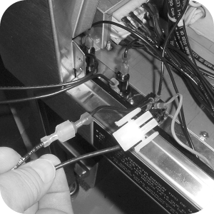
Locate the wire harness with the 3-pin white connector and plug the two wires onto the side terminals of the 15 amp fuse holders.
-
Locate the 2 wires with 90-degree blue connectors and place these on the center terminals of the fuse holders. Place the other end of the wires on L1 & L2 terminals of the primary (right) contactor.
-
-
For 400 volt fryers.
-
Locate the wire harness with the 3-pin white connector and plug one wire onto the side terminals of the 15 amp fuse holder or to wire #11 (CE units). Connect the other wire of the 3-pin connector to wire #3 using a wire nut. Refer to original wiring diagram.
-
Using one of the wires with 90-degree blue connectors, place it on the center terminal of the fuse holder. Place the other end of the wire on L1 of the primary (right) contactor.
-
-
For 480 volt fryers.
-
Locate the wire harness with the 3-pin white connector and connect the two wires to wires #1 and #3 from the step-down transformer. Refer to original wiring diagram
-
-
Locate the harness with the 2-pin white connector that has only one wire.
-
Install a spade connector on the portable filter receptacle wire that was cut from the 9-pin connector and connect it to the harness (If crimpers aren’t available use a wire nut).
-
Locate the wire harness with a white 12-pin box connector on one end and plug it into the transformer connector.
-
Ensure to plug the connector onto the correct voltage connector from the transformer.
-
Wire tie the wires to keep them from interfering with the components, except for the probe wire.
-
Plug in all connectors, including the probe and new transformer harness into the back of the control.
-
Using the self-tapping screws, provided in the kit, secure the controls to the unit, and the
-
unit is now ready for use.
Related Content
Testing and Replacing the Fuse Holders
Retrofit Control Instructions 290-590 KFC to 291-591 GM
Retrofit 292-592 Fast KFC to 291-591 Controls Instructions
FM08-481 8 Head Replacing the Control
FM08-502 8 Head Replacing KFC Control
Troubleshooting the SMS Control Online Projection System (OPS) Connection
Troubleshooting the C8000 Open Fryer Message
Troubleshooting the PFE 590 and 592 E-41 Control Programming Lost Error Code
Electric Power Cord Routing and Attachment Installation Instructions
PFE 592 (FAST Controls) to 590 (Henny Penny Controls) Retrofit Instructions
Direct-Connect Retrofit Instructions (For use on fryers after SN: 290-BE0401001 & 591- LG014JC)
PFE 590 and 591 Installing Optional Crumb Basket
Filter Rinse Hose Retrofit Instructions
Rear Cover Removal Instructions
Label Application and Location for the 8 Head Fryer
Testing and Replacing the Fuse Holders
Troubleshooting the PFE 591 E-41 Control Programming Lost Error Code
Reference
PFE 590 and 592 Inspection and Planned Maintenance