Applies to:
![]()
ALL CUSTOMERS
Label Application and Location for the 8 Head Fryer
Kit number
97347
Estimated Time
15 Minutes
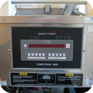
Label Placement Photos
-
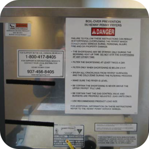
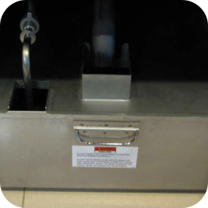
The following are examples of where the label should be applied
LABEL-WARNING HOT
LABEL-BOILOVER PREVENTION
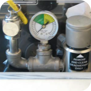
LABEL DEAD WT VALVE
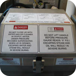
LABEL-LID INSTRUCTION ENG/FRE
LABEL-OPERATIONAL HAZARDS
LABEL - DANGER SHORTENING
LABEL-DANGER STIRRING
LABEL-Filter PAN WARNING
LABEL - BI-LING Filter VALVE
LABEL-WARNING DISC. POWER
Label Placement Instructions
-
For sound deadening follow these instructions
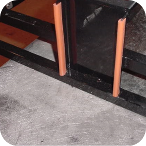
-
(MS01-511) placed on pump motor bracket (Orange grommet).
-
Peel or scrape off the old label or any remaining pieces.
-
Remove all grease and residue from the metal surface using a non-abrasive pad and a non-toxic detergent such as Dawn Platinum or Crystal Simple Green Industrial Cleaner. Use caution not to get any of the cleaning material in the cooking oil. THE SURFACE MUST BE COMPLETELY CLEAN IN ORDER FOR THE LABEL TO ADHERE.
-
Wipe over the cleaned area with a clean towel and water to remove any cleaner residue.
-
Dry the surface with a clean towel.
-
Peel one end of the backing away from the label and apply this exposed end to the proper position on the fryer.
-
Slowly peel the rest of the backing away from the label while smoothing the label into place. Be sure to work out any air bubbles and firmly press the label into position.
Related Content
PFE 590 and 591 Installing Optional Crumb Basket
Rear Cover Removal Instructions
Electric Power Cord Routing and Attachment Installation Instructions
PFE 590 and 591 Electronic Control Retrofit Computron 7000 to New Electronic Controls
PFE 592 (FAST Controls) to 590 (Henny Penny Controls) Retrofit Instructions
Direct-Connect Retrofit Instructions (For use on fryers after SN: 290-BE0401001 & 591- LG014JC)
Retrofit Control Instructions 290-590 KFC to 291-591 GM
Retrofit 292-592 Fast KFC to 291-591 Controls Instructions
Filter Rinse Hose Retrofit Instructions
FM08-481 8 Head Replacing the Control
FM08-502 8 Head Replacing KFC Control
Installing Optional Crumb Basket
PFG 690 Stabilizer Retrofit Instructions
I-Beam Cable Hole Plug Installation
PFG-69X & OFG-39X Gas Valve Replacement Kit
Repositioning/Rewiring Air Valves for 220240V Model 690/390 fryers
Repositioning / Rewiring Air Valves for 120V Model 690/390 fryers
FM07-558 Gas Valve Replacement Kit
PFG-690/691 & OFG-390/391 Pump Motor Relay Kit
Conversion From C8000 Control to KFC SMS Control
Manifold Retrofit Kit Instructions
Replace Nylatron Slides on PFG 690 and 691
PFG 690 and 691 Installing Filter Rinse Hose
PFG 690/691 Ignition Module Kit
Mounting the OFG 390 and PFG 690 Vacuum Switch
Conversion From Standard 690 Control to S/M Control
PFG 690 and 691 Temperature Probe CE Instructions
Replace Gas Valve Assembly with Gas Valve and Solenoid Assembly
Replacing Gas Valve Assembly With Gas Valve and Solenoid Assembly
Air Switch Monitoring Retrofit Kit Instructions
PFG 691 C8000 Retrofit Instructions
PFG 690 and 691 Lid Cable Replacement
Operating Instructions for PFG-691/OFG-391 Direct-Connect Oil System
Direct-Connect Retrofit Instructions (For use on fryers after SN: 391-LH016JC & 691-LH029JC)
CE Gas Valve Adjustment Instructions
Replacing High Limit Thermocouple
PFG 691 Attaching the Rinse Hose Instructions
Reference
PFE 590 and 592 Inspection and Planned Maintenance
PFE 590 and 592 KFC Annual Inspection Certification
PFE 591 Inspection and Planned Maintenance
PFG 690 and 692 Inspection and Planned Maintenance
PFG 690 and 692 KFC Annual Inspection Certification