Applies to:
![]()
ALL CUSTOMERS
Filter Rinse Hose Retrofit Instructions
Adjustable wrench
Crosstip head screwdriver
Pipe thread sealant
Kit number
14780
140000
Estimated Time
30 Minutes

|
To avoid electrical shock or property damage, move the power switch to OFF and disconnect power. |
|
|
Burn Risk Using PPE, remove hot oil from fryer before performing procedure or personal injury may occur. |
-
Use a crosstip head screwdriver to remove left side panel and rear panel from fryer.
-
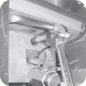
Use an adjustable wrench to loosen the side and front of fittings to the pump return line.
-
Loosen the filter motor mounting bolts, if necessary.
-
Unscrew the check valve assembly from vat.
-
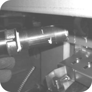
Locate the check valve assembly in the kit. Place pipe sealant on the threads of the nipple and screw the assembly into the vat and tighten.
-
Locate the filter inlet valve assembly in the kit. Place pipe sealant on the threads of the nipple and screw the assembly into the elbow of the check valve and tighten.
-
You may need to loosen the check valve assembly to a 45 degree angle to add the inlet valve assembly.
-
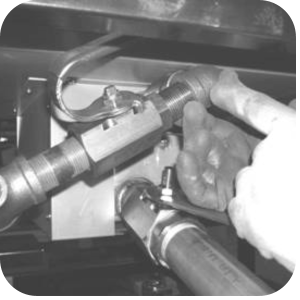
Locate the male connector rinse hose assembly in the kit and install it on the small side of the tee of the filter rinse hose assembly and tighten.
-
Locate the pump to check valve assembly in the kit and install it between the pump elbow and the filter rinse hose assembly. Tighten all fittings with a wrench.
-
If the filter pump motor mounting bolts are loose, they must be tightened at this time. Lift up on the motor when tightening the bolts, or the motor will interfere with the filter pan.
-
Unit is now ready for use.
Related Content
Testing and Replacing the Power/Pump Switch
Replacing the Drain Microswitch
Replacing the Drain Valve and Extension
Direct-Connect Retrofit Instructions (For use on fryers after SN: 290-BE0401001 & 591- LG014JC)
Troubleshooting the PFE 590 and 592 Not Pumping Error Code
Electric Power Cord Routing and Attachment Installation Instructions
PFE 590 and 591 Electronic Control Retrofit Computron 7000 to New Electronic Controls
PFE 592 (FAST Controls) to 590 (Henny Penny Controls) Retrofit Instructions
Retrofit Control Instructions 290-590 KFC to 291-591 GM
Retrofit 292-592 Fast KFC to 291-591 Controls Instructions
PFE 590 and 591 Installing Optional Crumb Basket
Rear Cover Removal Instructions
Label Application and Location for the 8 Head Fryer
FM08-481 8 Head Replacing the Control
FM08-502 8 Head Replacing KFC Control
Testing and Replacing the Power/Pump Switch
Replacing the Drain Microswitch
Replacing the Drain Valve and Extension
Troubleshooting the PFE 591 E-15 Drain Open Error Code
Troubleshooting the PFE 591 Oil Not Pumping Error Code
Reference
PFE 590 and 592 Inspection and Planned Maintenance