Applies to:
![]()
ALL CUSTOMERS
Retrofit Control Instructions 290-590 KFC to 291-591 GM
5/8 in. Socket
Crosstip head screwdriver
Flat-head screwdriver
Electric drill
Rivet tool
Wire strippers/crimpers
Kit number
14686
14687
14688
Estimated Time
1 Hour

|
To avoid electrical shock or property damage, move the power switch to OFF and disconnect power. |
Installation of this kit should be preformed only by a qualified service technician
-
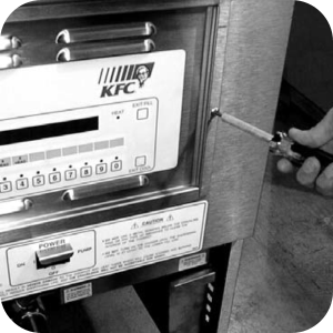
Remove 2 screws from the control panel
-
Lift panel up and out.
-
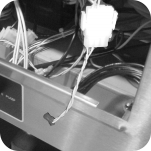
Unplug the 9-pin connector and the probe connection at the control board.
-
Remove control from unit.
-
Remove the 3 screws securing the inner heat shield and remove heat shield from unit.
-
Locate the wire harness with the 6-pin red connector.
-
Connect the yellow wires to high limit wires using wire nuts.
-
Connect the white wires to the drain switch wires using wire nuts.
-
-
Locate the wire harness with the 12 pin red connector.
-
For 590s only, connect the pressure solenoid wires to the red wires in positions 1& 2 of the 12 pin connector.
-
Ensure these are not connected to the pump by accident. When retrofitting a 290, install wire nuts on these red wires to insulate them.
-
Connect the yellow wires in position 6 & 7 of the 12-pin connector to the coil of the Primary Contactor.
-
Connect the blue wires in positions 11 & 12 of the 12 pin connector to the coil of Secondary Contactor.
-
-
Locate the wire harness with the 3-pin white connector and plug the two wires onto the side terminals of the 15 amp fuse holders. Remove and discard the wires from the top terminal of the fuses and replace with wires L1- 1 & L2-1, from the kit. This supplies power to the control and pump.
-
The wires in the wire harnesses are marked to guide you in positioning the wires correctly. 400V, Y configuration fryers (wiring diagram 69662) cut the terminal off of wire L2F and replace it with a ring terminal, provided in the kit. Attach L2F to the neutral side of the elements (buss bar).
-
Locate the harness with the 2-pin white connector with wires marked M1 & M2. Attach these wires to the filter motor wires, at the conduit on the left side of the control area, using wire nuts. Connect the 4-pin to 2-pin adaptor to the probe connector.
-
Remove the 2 top and 3 bottom crosstip head screws which secures the outer front shroud.
-
Pull wires from POWER switch.
-
Pull down on outer front shroud and remove from unit.
-
Using self-tapping screws, provided in the kit, mount the transformer.
-
Locate the 5-pin connector and attach the wires to the power switch as shown in the wiring diagrams provided in the kit.
-
Wire tie the wires to keep them from interfering with the components, except for the probe wire.
-
Slide the top of the outer front shroud underneath the lip on the countertop, and press into place. Secure with screws previously removed.
-
Plug in all connectors, including the probe and new transformer harness into the back of the control.
-
Slide the top of the control panel underneath the lip on the countertop and then press into place.
-
Using the screws, provided in the kit, secure the controls to the unit.
-
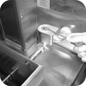
Remove the retaining clip from the top of the solenoid coil housing and remove the cover.
-
Pull the coil housing from solenoid and remove the coil.
-
Replace coil with the low voltage coil supplied in the kit. Ensure to replace the spacers from the old coil onto the new coil.
-
When retrofitting an OFE-292, ignore steps and references to the pressure solenoid and wires.
-
Using 5/8 inch socket, remove the deadweight orifice from the deadweight and replace it with the 9 lb. deadweight orifice from the kit
-
Remove and discard the deadweight from the deadweight assembly and replace with the deadweight from the kit.
-
Drill-out the rivets securing the Boil-Over chart on the back shroud and replace with Boil-Over chart in the kit.
-
Remove the filtering label, below the control panel, and replace with the Power/Off/Pump label from the kit.
-
The unit is now ready for use.
Related Content
Testing and Replacing the Fuse Holders
PFE 590 and 591 Electronic Control Retrofit Computron 7000 to New Electronic Controls
Retrofit 292-592 Fast KFC to 291-591 Controls Instructions
FM08-481 8 Head Replacing the Control
FM08-502 8 Head Replacing KFC Control
Troubleshooting the SMS Control Online Projection System (OPS) Connection
Troubleshooting the C8000 Open Fryer Message
Troubleshooting the PFE 590 and 592 E-41 Control Programming Lost Error Code
Electric Power Cord Routing and Attachment Installation Instructions
PFE 592 (FAST Controls) to 590 (Henny Penny Controls) Retrofit Instructions
Direct-Connect Retrofit Instructions (For use on fryers after SN: 290-BE0401001 & 591- LG014JC)
PFE 590 and 591 Installing Optional Crumb Basket
Filter Rinse Hose Retrofit Instructions
Rear Cover Removal Instructions
Label Application and Location for the 8 Head Fryer
Testing and Replacing the Fuse Holders
Troubleshooting the PFE 591 E-41 Control Programming Lost Error Code
Reference
PFE 590 and 592 Inspection and Planned Maintenance