The gas control valve sends regulated gas to the burners when the controller calls for heat. The control valve can be turned on or off. In the on position, and the power switch on, a spark ignitor lights a standing pilot, and when the control calls for heat, the valve is opened and the burners are ignited.

|
To avoid personal injury or property damage, before starting this procedure, move the main power switch to the off position. Disconnect the main circuit breakers at the circuit breaker box or unplug service cord from wall receptacle. |
A voltage check at the gas control valve must be taken four (4) seconds after the POWER switch is turned to the ON position.
-
Turn gas knob to the OFF position.
-
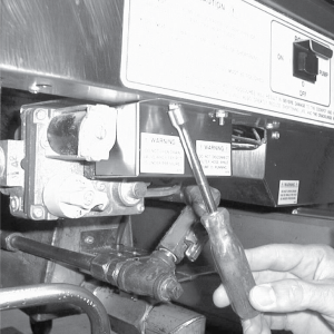
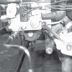
Remove cover from control valve.
-
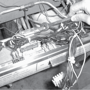
Remove the wires from the control valve.
-
Remove left side panel.
-
Remove control panel.
-
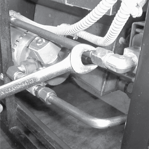
Unscrew nut from inlet line from the control valve.
-
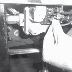
Remove the bracket from behind the gas control valve.
-
Remove pilot light tube from gas control valve.
-
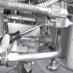
Loosen fittings from tee and pull control valve assembly from the unit.
-
Remove the fittings from the defective control valve, and place fittings on new valve.
-
Reassemble in reverse order.
Related Content
Replacing the High Temperature Limit Control
Replacing the Temperature Probe
Replacing the Flame Sensor Assembly
Replacing the Ignitor Assembly
Replacing the Ignition Modules
Replacing High Limit Thermocouple
PFG-69X & OFG-39X Gas Valve Replacement Kit
Repositioning/Rewiring Air Valves for 220240V Model 690/390 fryers
Repositioning / Rewiring Air Valves for 120V Model 690/390 fryers
FM07-558 Gas Valve Replacement Kit
Manifold Retrofit Kit Instructions
PFG 690/691 Ignition Module Kit
Mounting the OFG 390 and PFG 690 Vacuum Switch
PFG 690 and 691 Temperature Probe CE Instructions
Replace Gas Valve Assembly with Gas Valve and Solenoid Assembly
Replacing Gas Valve Assembly With Gas Valve and Solenoid Assembly
Air Switch Monitoring Retrofit Kit Instructions
CE Gas Valve Adjustment Instructions
Troubleshooting the PFG 690 and 692 E-4 Control Overheating Error Code
Troubleshooting the PFG 690 and 692 E-5 Oil Overheating Error Code
Troubleshooting the PFG 690 and 692 E-6 Temperature Probe Error Code
Troubleshooting the PFG 690 and 692 E-10 High Limit Error Code
Reference
PFG 690 and 692 Inspection and Planned Maintenance