The unit has electronic spark ignition, that lights a standing pilot.

|
To avoid electrical shock or property damage, move the power switch to OFF and disconnect power. |
|
NOTICE - |
To avoid property damage, do not tamper with this component. It is factory sealed and should not be adjusted. |
-
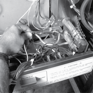
Remove the electrical power supplied to the unit.
-
Remove the control panel.
-
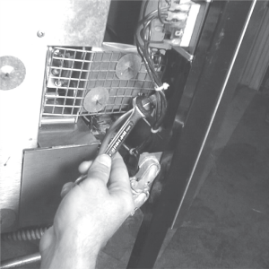
Disconnect the 1/4” gas line fitting from the pilot assembly.
-
Follow the wire from the spark ignitor to the module, and remove the wire from the module.
-
Remove the left, or right side panel, depending upon which ignitor assembly to be removed.
-
Disconnect gas line (for the left ignitor assembly).
-
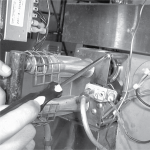
Remove the 4 screws securing the burner assembly, and pull the assembly from the unit.
-
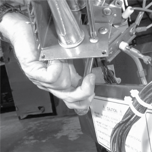
Using a crosshead screwdriver, remove the screw securing the ignitor assembly to the burner assembly, and pull the ignitor assembly from the unit.
-
Secure the new assembly with the screw previously removed, making sure the assembly is turned to provide a 1/8” gap between the spark ignitor and the hood of the pilot assembly.
Related Content
Replacing the High Temperature Limit Control
Replacing the Temperature Probe
Replacing the Gas Control Valve
Replacing the Flame Sensor Assembly
Replacing the Ignition Modules
Replacing High Limit Thermocouple
PFG-69X & OFG-39X Gas Valve Replacement Kit
Repositioning/Rewiring Air Valves for 220240V Model 690/390 fryers
Repositioning / Rewiring Air Valves for 120V Model 690/390 fryers
FM07-558 Gas Valve Replacement Kit
Manifold Retrofit Kit Instructions
PFG 690/691 Ignition Module Kit
Mounting the OFG 390 and PFG 690 Vacuum Switch
PFG 690 and 691 Temperature Probe CE Instructions
Replace Gas Valve Assembly with Gas Valve and Solenoid Assembly
Replacing Gas Valve Assembly With Gas Valve and Solenoid Assembly
Air Switch Monitoring Retrofit Kit Instructions
CE Gas Valve Adjustment Instructions
Troubleshooting the PFG 690 and 692 E-4 Control Overheating Error Code
Troubleshooting the PFG 690 and 692 E-5 Oil Overheating Error Code
Troubleshooting the PFG 690 and 692 E-6 Temperature Probe Error Code
Troubleshooting the PFG 690 and 692 E-10 High Limit Error Code
Reference
PFG 690 and 692 Inspection and Planned Maintenance