This high temperature control is a safety, manual reset control, which senses the temperature of the oil. If the oil temperature exceeds 425°F (218°C), this switch opens and shuts off the heat to the vat. When the temperature of the oil drops to a safe operation limit, manually reset by pressing the red reset button. The red reset button is located under the control panel, in the front of the fryer, to the right of the drain. Once reset, the vat starts heating.
Before testing or replacing a high temperature limit control, check to see that its circuit is closed.

|
To avoid electrical shock or property damage, move the power switch to OFF and disconnect power. |
Testing
-
Remove electrical power supplied to the fryer.
-
Remove the control panel.
-
Remove the inner heat shield.
-
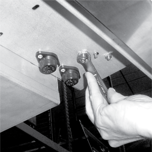
Remove the two nuts securing the high limit bracket to the unit, and pull the bracket from the unit.
-
Remove the two screws securing the high limit to the bracket, and remove the high limit from the bracket.
-
Remove the two electrical wires from the high temperature limit control.
-
Manually reset the control, then check for continuity between the two terminals after resetting the control. If the circuit is open, replace the control, then continue with this procedure. (If the circuit is closed, the high limit is not defective. Reconnect the two electrical wires.)
Replacing
-
If the tube is broken or cracked, the control will open, shutting off electrical power. The control cannot be reset.
-
Drain oil from the vat and discard. A substance in the tube could contaminate the oil.
-
Remove control panel.
-
Loosen small inside screw nut on capillary tube.
-
Remove capillary bulb from bulb holder inside the vat.
-
Straighten the capillary tube.
-
Remove larger outside nut that threads into vat wall, and remove defective control from control panel area.
-
Insert new control and replace screws.
Shock Hazard
To avoid electrical shock, the capillary tube should never touch electrical wires or terminals.
-
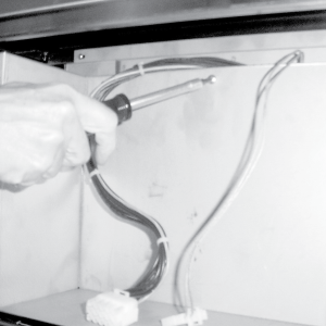
Uncoil capillary line, starting at capillary tube, and insert through vat wall.
-
Carefully bend the capillary tube as shown in photo and place into bulb brackets.

To avoid personal injury or equipment damage, capillary bulb must remain in the clip provided on the front wall of the vat.
-
Pull excess capillary line from vat and tighten nut into vat wall.
-
With excess capillary line pulled out, tighten smaller nut.
-
Replace timer and front panels.
-
Refill vats with oil.
Related Content
Replacing the Temperature Probe
Replacing the Gas Control Valve
Replacing the Flame Sensor Assembly
Replacing the Ignitor Assembly
Replacing the Ignition Modules
Replacing High Limit Thermocouple
PFG-69X & OFG-39X Gas Valve Replacement Kit
Repositioning/Rewiring Air Valves for 220240V Model 690/390 fryers
Repositioning / Rewiring Air Valves for 120V Model 690/390 fryers
FM07-558 Gas Valve Replacement Kit
Manifold Retrofit Kit Instructions
PFG 690/691 Ignition Module Kit
Mounting the OFG 390 and PFG 690 Vacuum Switch
PFG 690 and 691 Temperature Probe CE Instructions
Replace Gas Valve Assembly with Gas Valve and Solenoid Assembly
Replacing Gas Valve Assembly With Gas Valve and Solenoid Assembly
Air Switch Monitoring Retrofit Kit Instructions
CE Gas Valve Adjustment Instructions
Troubleshooting the PFG 690 and 692 E-4 Control Overheating Error Code
Troubleshooting the PFG 690 and 692 E-5 Oil Overheating Error Code
Troubleshooting the PFG 690 and 692 E-6 Temperature Probe Error Code
Troubleshooting the PFG 690 and 692 E-10 High Limit Error Code
Reference
PFG 690 and 692 Inspection and Planned Maintenance