The ignition modules send 24 volts to the ignitors and gas valve.
Three different modules are in the field.
The White Rogers and Fenwall modules have a red LED, and the Robertshaw modules have a green LED. These LEDs help to identify a failure.

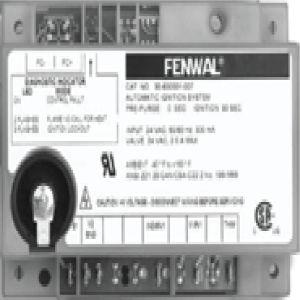
For the White Rogers’

For the Robertshaw, when the control calls for heat, the LED will be on continuously, indicating the control is functional. If the LED flashes, the module did not sense a pilot flame. If the LED goes out while the control is calling for heat, an internal fault had been detected, and the module should be replaced.

|
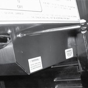
To avoid electrical shock or property damage, move the power switch to OFF and disconnect power. |
|
NOTICE - |
To avoid property damage, do not tamper with this component. It is factory sealed and should not be adjusted. |
-
Remove the electrical power supplied to the unit.
-
Remove the control panel
-
Remove the condensation drain pan.
-
Using a crosshead screwdriver, remove the screws securing the module cover and remove the cover.
-
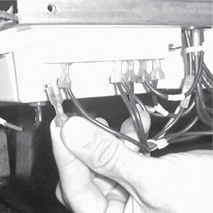
Label and remove the wires from the module.
-
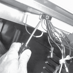
Using a 3/8” socket and crosshead screwdriver, remove the nuts and screws securing the module and remove it from the unit.
-
Replace with module in reverse order.
Related Content
Replacing the High Temperature Limit Control
Replacing the Temperature Probe
Replacing the Gas Control Valve
Replacing the Flame Sensor Assembly
Replacing the Ignitor Assembly
Replacing High Limit Thermocouple
PFG-69X & OFG-39X Gas Valve Replacement Kit
Repositioning/Rewiring Air Valves for 220240V Model 690/390 fryers
Repositioning / Rewiring Air Valves for 120V Model 690/390 fryers
FM07-558 Gas Valve Replacement Kit
Manifold Retrofit Kit Instructions
PFG 690/691 Ignition Module Kit
Mounting the OFG 390 and PFG 690 Vacuum Switch
PFG 690 and 691 Temperature Probe CE Instructions
Replace Gas Valve Assembly with Gas Valve and Solenoid Assembly
Replacing Gas Valve Assembly With Gas Valve and Solenoid Assembly
Air Switch Monitoring Retrofit Kit Instructions
CE Gas Valve Adjustment Instructions
Troubleshooting the PFG 690 and 692 E-4 Control Overheating Error Code
Troubleshooting the PFG 690 and 692 E-5 Oil Overheating Error Code
Troubleshooting the PFG 690 and 692 E-6 Temperature Probe Error Code
Troubleshooting the PFG 690 and 692 E-10 High Limit Error Code
Reference
PFG 690 and 692 Inspection and Planned Maintenance