Applies to:
![]()
ALL CUSTOMERS
Mounting the OFG 390 and PFG 690 Vacuum Switch
-
Drill with cross tip
-
Needle nose pliers
-
Measuring tape
Kit number
Estimated Time
30 Minutes
 Only perform this procedure when the unit is cool or severe burns may result.
IMPORTANT! For proper function, vacuum switch MUST BE MOUNTED in the orientation as shown in these instructions.
-
Turn power switch off.
-
Ensure fryer is cool to the touch before moving.
-
Pull out the fryer and unplug from power source.
-
Using the drill with a cross tip, remove control mounting screw(s) and carefully lower control down.
-
Disconnect the tubing and two wires from the existing vacuum switch.
-
Remove the existing vacuum switch.
-
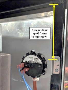
Measure 5 inches from top of frame to first hole location and position switch as shown. Mount using the two self-drilling screws supplied in the kit.
-
Reconnect the tubing and wires.
-
Working in reverse, complete steps 4 through 1 and return fryer to service.
NOTE: Vacuum switch appearance may vary by component supplier, but the mounting position is the same.
NOTE: Wires may be attached to either terminal.
Related Content
Replacing the High Temperature Limit Control
Replacing the Temperature Probe
Replacing the Gas Control Valve
Replacing the Flame Sensor Assembly
Replacing the Ignitor Assembly
Replacing the Ignition Modules
Replacing High Limit Thermocouple
PFG-69X & OFG-39X Gas Valve Replacement Kit
Repositioning/Rewiring Air Valves for 220240V Model 690/390 fryers
Repositioning / Rewiring Air Valves for 120V Model 690/390 fryers
FM07-558 Gas Valve Replacement Kit
Manifold Retrofit Kit Instructions
PFG 690/691 Ignition Module Kit
PFG 690 and 691 Temperature Probe CE Instructions
Replace Gas Valve Assembly with Gas Valve and Solenoid Assembly
Replacing Gas Valve Assembly With Gas Valve and Solenoid Assembly
Air Switch Monitoring Retrofit Kit Instructions
CE Gas Valve Adjustment Instructions
Troubleshooting the PFG 690 and 692 E-4 Control Overheating Error Code
Troubleshooting the PFG 690 and 692 E-5 Oil Overheating Error Code
Troubleshooting the PFG 690 and 692 E-6 Temperature Probe Error Code
Troubleshooting the PFG 690 and 692 E-10 High Limit Error Code
I-Beam Cable Hole Plug Installation
FM08-502 8 Head Replacing KFC Control
FM08-481 8 Head Replacing the Control
Label Application and Location for the 8 Head Fryer
PFG-690/691 & OFG-390/391 Pump Motor Relay Kit
Conversion From C8000 Control to KFC SMS Control
Rear Cover Removal Instructions
Replace Nylatron Slides on PFG 690 and 691
Installing Optional Crumb Basket
PFG 690 and 691 Installing Filter Rinse Hose
PFG 690 Stabilizer Retrofit Instructions
Conversion From Standard 690 Control to S/M Control
PFG 691 C8000 Retrofit Instructions
PFG 690 and 691 Lid Cable Replacement
Operating Instructions for PFG-691/OFG-391 Direct-Connect Oil System
Direct-Connect Retrofit Instructions (For use on fryers after SN: 391-LH016JC & 691-LH029JC)
Reference
PFG 690 and 692 Inspection and Planned Maintenance