Applies to:

ALL CUSTOMERS
 Required tools
-
Wrench or Crows Foot: 11/16 in (18 mm), 1/2 in (13 mm)
-
Torque Wrench (In-lb): 1/2 in (13 mm)
-
Crosstip Screwdriver
-
Drill with crosstip bit
-
Needle nose pliers
-
White Loctite® 567 thread sealant
Kit contentsHigh-Limit Thermocouple Probe
Kit number
179097
Estimated Time
1 hour

|
Only perform this procedure when the unit is cool or severe burns may result. |
Preparing Fryer
-
Turn power switch off.
-
Ensure fryer is cool to touch before moving.
-
Pull out the fryer and unplug from power source.
-
Remove oil from the fryer.
-
Verify drain pan is underneath fryer and empty.
-
Using PPE, slowly open the drain valve and allow the vat to empty completely.
-
-
Lower front display control, disconnect wiring, and set aside.
Removing Existing High Limit Thermocouple
-
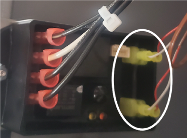
Using needle nose pliers, disconnect the thermocouple wires from module.
-
Using a crosstip screwdriver, loosen and remove the brackets holding the high limit probe on the element.
-
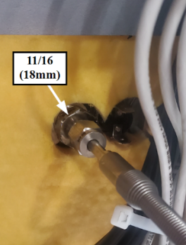
Using an 11/16 in (18 mm) wrench or crows foot, remove the thermocouple fitting from vat and remove probe from fryer.
-
Apply white thread sealant to new high limit probe bushing, angle probe and insert into vat. Thread bushing into vat and tighten using an 11/16 in (18 mm) wrench or crows foot.
-
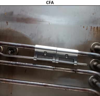
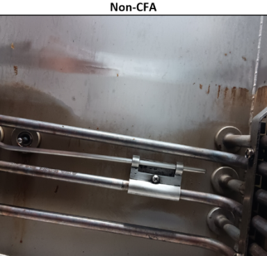
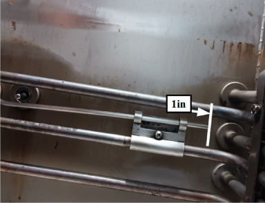
Install the high limit probe into the mounting bracket(s) on the correct element making sure the probe sits beneath the temperature probe. Make sure first bracket sits 1 inch from the end of the probe and tighten screws.
-
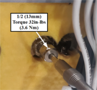
Using a 1/2 in (13 mm) torque wrench, torque the high limit compression fitting to 32 in-lbs (3.6 Nm).
-
Working in reverse order, complete step 1 in the Removing Existing High Limit Thermocouple section, and steps 5 through 1 in the Preparing Fryer section.
|
|
NOTE: For Chick-fil-A fryers, there will be two brackets holding the probe from the top element. For all open fryers, there will be one bracket holding the probe on the middle element.
Related Content
Replacing the High Temperature Limit Control
Calibrating The Standard Single Stage Thermostat
Replacing the Temperature Probe
Replacing the Heating Elements
Replacing the Heating Contactors
Replacing the Main Power Switch
Temperature Probe Gauge Instructions
Troubleshooting the PFE 500 and 561 E-5 Oil Overheating Error Code
Troubleshooting PFE 561 E-6 Temperature Probe Error Code
Troubleshooting PFE 561 E-10 High Limit Error Code
Troubleshooting PFE 500 and 561 E-26 Heat Amps Locked On Error Code
Troubleshooting an E-92 Error Code
Troubleshooting PFE 561 E-92 24V Current Limiter (Fuse) Trip Error Code
Troubleshooting Oil Melting or Heating Slowly
Troubleshooting PFE 500 W-1 Low Voltage Warning
Troubleshooting PFE 500 W-2 Slow Heating Warning
Troubleshooting PFE 500 W-3 Was Not Ready Warning
Troubleshooting PFE 500 W-4 Slow Cooking Warning
Troubleshooting PFE 500 W-5 Slow Cooking Warning
Troubleshooting PFE 500 W-6 Slow Cooking Warning
Troubleshooting PFE 500 W-9 Discard Product Warning
Direct connect oil system operating instructions
Electronic C2000 Simple Control Retrofit Kit
4 Head PFE 500/ PFG 600 Removing the Lid
RLink programming instructions
Pressure Assist Kit Installation
PFE 500/PFG 600 Wi-Fi Verification and Troubleshooting Instructions
PFE 500/PFG 600 Hybrid Control Installation Instructions
2nd Generation Radio for SMS: Hardware Installation
2nd Generation Radio for SMS: Software Update
FM08-748 2nd Generation Radio for SMS: Troubleshooting
Instructions for Fryer Control Replacement Kits
SMS 20 Auto Polish Programming Instructions
CFA PFE 500 Hybrid Wi-Fi Status Check
Reference