SMS Retrofit kit
Crosstip screwdriver
Electric drill
Wire cutters or wire strippers
1-1/8 in. Greenlee hole punch
3/16 in. drill bit
9/19 in. drill bit
Kit number
14789
14790
14791
14792
14793
14794
14795
14796
14797
14798
14799
14800
14801
14802
14803
14804
14805
14806
14807
14808
14809
14810
14811
14812
14813
14814
14815
14816
14817
14818
14819
14820
14821
14822
14823
14824
14825
14826
14827
14828
14829
14830
14831
14832
14833
14834
14835
14836
14837
14838
14839
14840
14841
14842
14843
14843
14844
14845
14846
14847
14848
Estimated Time
1 Hour

|
To avoid electrical shock or property damage, move the power switch to OFF and disconnect power. |
-
Installation should only be preformed by a qualified service technician.
-
Drain oil from vat.
-
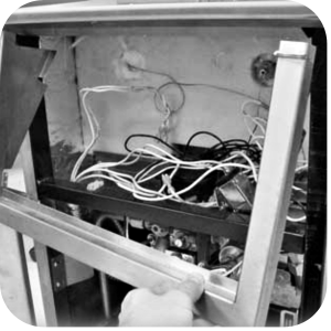
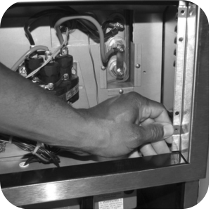
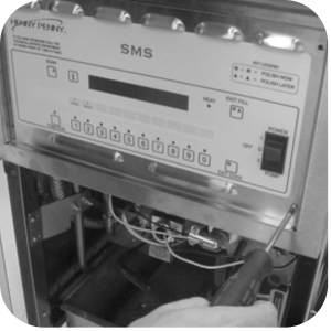
Remove the crosstip screws from the control panel, and remove the control from unit.
-
For 500 fryers SN: HB014JB and above and 600 fryers SN: GA086JB and above skip the following steps.
-
Remove the two screws securing the control shroud from the unit.
-
For gas model 600 fryers, remove the three screws securing the shield under the front of the counter top and pull shield from unit.
-
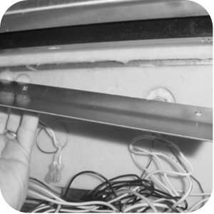
Install new control shroud provided in kit.
-
Remove the fuse holders from the panels.
-
For non-CE units locate space on the shroud behind the control panel to drill or punch two, 1-1/8 in. holes to remount the fuse holders.
-
Punch holes and place the fuse holders in holes.
-
Mark screw mounting holes and use a 3/16 in. drill bit to drill-out the holes.
-
Mount fuse holders with screws and nuts.
-
-
For CE units locate space on the shroud behind the control panel and drill 1, 9/16 in. hole to remount the fuse holder.
-
Drill hole and snap fuse holder in place.
-
-
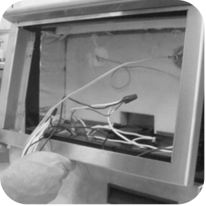
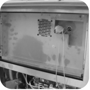
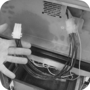
For 500 fryers SN: HB014JB and above and 600 fryers SN: GA086JB Start here. Carefully place new internal shroud into control panel area, pulling the probe wires through the round hole and the 9-pin connector through the center of the shroud.
-
Secure the shroud with four screws provided in the kit.
-
For units that do not have weld-nuts present to mount the internal shroud. Use the four Tinnerman clips in the kit and push them onto the shroud.
-
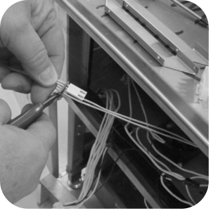
Add the wire assembly extension on the electrical.
-
Cut the connector off the probe wires, strip to a length of 3/8 in.
-
Wire nut to the new probe connector provided in the kit.
-
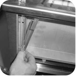
Slide the control panel brackets between the outer and inner control shrouds.
-
Secure with screws provided in the kit (Some models may have this bracket).

-
Plug wire assembly extension and probe onto new control.
-
Place new control on fryer. Line up holes in the panel with the holes on the bracket. Secure with screws provided in the kit.
-
Remove the old wiring diagram from the door of the fryer.
-
Re-connect electrical supply to fryer.
Unit is ready for use.
Related Content
Replacing the Indicator Lights
Replacing the Main Power Switch
Electronic C2000 Simple Control Retrofit Kit
RLink programming instructions
PFE 500/PFG 600 Hybrid Control Installation Instructions
PFE 500/PFG 600 Wi-Fi Verification and Troubleshooting Instructions
2nd Generation Radio for SMS: Hardware Installation
2nd Generation Radio for SMS: Software Update
FM08-748 2nd Generation Radio for SMS: Troubleshooting
Instructions for Fryer Control Replacement Kits
SMS 20 Auto Polish Programming Instructions
CFA PFE 500 Hybrid Wi-Fi Status Check
Troubleshooting the SMS 20 Control Countdown
Troubleshooting the SMS Control Online Projection System (OPS) Connection
Troubleshooting the Filter Count Not Reducing with Each Drop
Troubleshooting the PFE 500 and 561 E-41 Programming Settings Lost Error Code
Direct connect oil system operating instructions
4 Head PFE 500/ PFG 600 Removing the Lid
Pressure Assist Kit Installation
Temperature Probe Gauge Instructions
Replacing the Indicator Lights
Replacing the Main Power Switch
Installation of PFG 600 and PFG 600 SSI FM07-366 Electromechanical to C1000 Retrofit
PFG 600 SSI Electronic C1000 to C8000 Retrofit Kit
Hybrid Control and Wi-Fi Installation
Troubleshooting the SMS Control Online Projection System (OPS) Connection
Troubleshooting the PFG 600 E-41 Control Programming Lost Error Code
Direct connect retrofit PFG 600
Direct connect retrofit PFG-600
PFG 600 Ignition Module Retrofit Kit
PFG 600 SSI Fryers Gas Valve Replacement Kit
SAE Thread Filter Pump Installation
Pre VA SAE Thread Filter Pump Installation
Reference
PFE 500 and 561 Inspection and Planned Maintenance
PFE 500 KFC Annual Inspection Certification