Direct connect oil system operating instructions
Kit number
14365
14366
14369
14370
14425
14426
14696
24658
24659
Estimated Time
30 Minutes
-
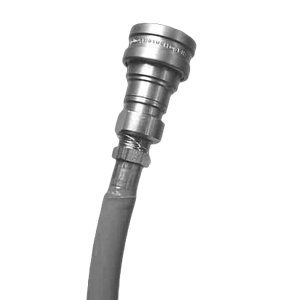
Connect the female quick disconnect, that is attached to the hose in the rear of the fryer, to the correct male quick disconnect at the wall. Once attached the hose can remain connected unless the fryer is moved.
-
Open the drain valve and drain the oil from the unit, into the drain pan.
-
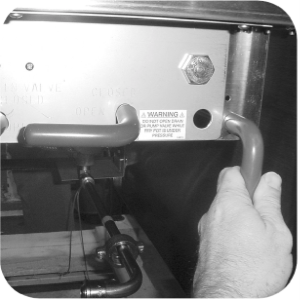
Once all oil is drained, turn the red handle counterclockwise, into the position and hold.
-
While holding the handle down, turn the power/pump switch to the pump position. Oil will now be pumping into the drain pan.
-
Once all the oil is out of the drain pan, turn the power/pump switch to the off position.
-
Turn red handle back to original position.
-
Unit is now ready for fresh oil.
Related Content
Replacing The Filter Rinse Hose
Preventing Filter Pump Problems
Troubleshooting an E-92 Error Code
Troubleshooting the PFE 500 and 561 Not Pumping Error Code
Troubleshooting the PFE 500 and 561 E-15 Drain Open Error Code
Electronic C2000 Simple Control Retrofit Kit
4 Head PFE 500/ PFG 600 Removing the Lid
RLink programming instructions
Pressure Assist Kit Installation
PFE 500/PFG 600 Wi-Fi Verification and Troubleshooting Instructions
PFE 500/PFG 600 Hybrid Control Installation Instructions
2nd Generation Radio for SMS: Hardware Installation
2nd Generation Radio for SMS: Software Update
FM08-748 2nd Generation Radio for SMS: Troubleshooting
Instructions for Fryer Control Replacement Kits
SMS 20 Auto Polish Programming Instructions
Temperature Probe Gauge Instructions
CFA PFE 500 Hybrid Wi-Fi Status Check
PFG 600 Preventing Filter Pump Problems
Replacing the Filter Rinse Hose
SAE Thread Filter Pump Installation
Pre VA SAE Thread Filter Pump Installation
Troubleshooting the PFG 600 Oil Not Pumping Error Code
Troubleshooting the PFG 600 E-15 Drain Open Error Code
Installation of PFG 600 and PFG 600 SSI FM07-366 Electromechanical to C1000 Retrofit
PFG 600 SSI Electronic C1000 to C8000 Retrofit Kit
Direct connect retrofit PFG 600
Direct connect retrofit PFG-600
PFG 600 Ignition Module Retrofit Kit
PFG 600 SSI Fryers Gas Valve Replacement Kit
Hybrid Control and Wi-Fi Installation
Reference
PFE 500 and 561 Inspection and Planned Maintenance
PFE 500 KFC Annual Inspection Certification