Electronic C2000 Simple Control Retrofit Kit
Adjustable wrench
Center punch and Hammer
Crosstip screwdriver
Pipe thread sealant
Ratchet and extension
Wire cutter stripper
#8-32 Tap
9/64 in. Drill bit and drill
11/16 in. Crowsfoot socket
Kit number
14896
14934
Estimated Time
1.5 to 2 hours

|
To avoid electrical shock or property damage, move the power switch to OFF and disconnect power. |
-
Drain oil from unit.
-
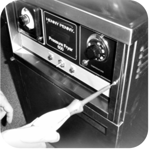
Remove the crosstip screws from the control panel.
-
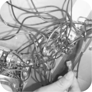
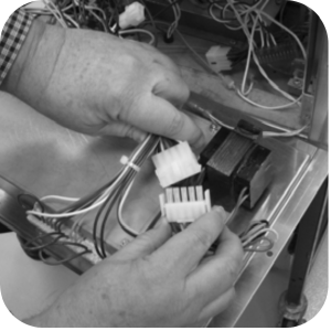
Cut wire ties and mark the wires to the pump connected to the power switch and unplug.
-
Mark and disconnect the wires to the pressure solenoid, at the N/C terminals on the timer.
-
Remove thermostat bulb, capillary and bracket form the elements and pull from fryer.
-
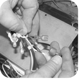
Disconnect and remove the remaining control wires and connectors.
-
Disconnect remaining power switch and indicator light wires.
-
Disconnect drain switch and high limit wires and label for later use.
-
Cut and strip wires.
-
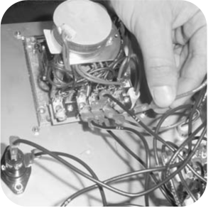
Disconnect 15 amp fuse holder wires from primary contactor and remaining coil wires.
-
Disconnect coil wires from the heat contactor.
-
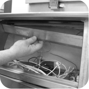
Pull "old" control from unit.
-
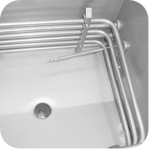
Locate 3 in. probe from kit and install temperature probe.

Excess force will damage the temperature probe.
-
Insert probe to 1/8 in. from the outer surface of the elements. Ensure it does not extend beyond this or the basket will catch and bend. If not extended enough into the vat, the temperature readings will be lower than the actual temperature.
-
Do not over tighten the compression nut, this can cause the ferrule to distort the probe sheath.
-
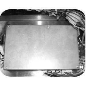
Before installing the two sheets of insulation, ensure all grease build-up is clean.
-
Install two sheets of insulation against the vat wall. Use thin sheets first.

-
For Bent front panels, SN: KB020JJ and below.
-
Locate the new control from kit.
-
Center panel in control area of fryer. Align the top edge with the edge of the counter top.
-
While holding the panel in place, mark the mounting holes on each side.
-
Using a center-punch, punch each hole.
-
Using a 9/64 in. drill bit, drill both holes.
-
Using a #8-32 tap, tap-out both holes.
-
-
For flat front panels SN: KB021JJ to HB013JB no drilling is required.
For flat front panels SN: HB014JB and above.
-
Locate the new control from kit.
-
Center panel in control area of fryer, resting the bottom of the panel on the bottom of control.
-
While holding the panel in place, mark the mounting holes on each side.
-
Using a center-punch, punch each hole.
-
Using a 9/64 in. drill bit, drill both holes.
-
Using a #8-32 tap, tap-out both holes.
-
-
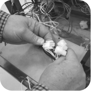
Locate wires H/L-1, and H/L-2(red) from the 12-pin connector and connect to the high limit wires using wire nuts.
-
Locate wires DS1 and DS2 (brown) from the 12-pin connector and connect to the drain switch wires using wire nuts.
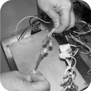
-
Connect the two probe terminals to the terminals from the probe connector.
-
Locate wires SFTY1 and SFTY2 (Yellow) from the 12-pin connector and connect to the primary safety contactor.
-
Locate wires P1 and P2 (red) from the 6-pin connector and connect to the pressure solenoid wires.
-
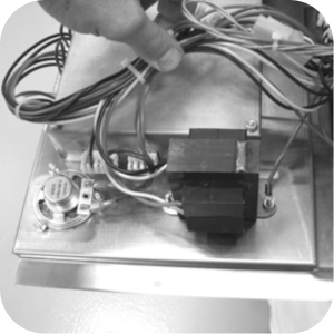
Locate the 240V transformer from the kit and mount to the back of the panel.
-
Connect transformer to wiring harness.
-
Locate wires 120/240 and 208 on transformer harness.
-
For 208 volt fryers, connect the 208 wire to L1-2.
-
For 220, 230, or 240 volt fryers, connect 120/240 to L1-2.
-
-
For 208-240 Volte contactors, Use the 2-pin connector with black and white wires N1-5 and L1-5 to connect the 2-pin connector VIN1 and VIN2.
-
For 24 Volt contactors use the 2-pin connector on harness with blue and yellow wires 24V-1 and 24VC-1 to connect the 2-pin connector VIN1 and VIN2.
-
Cut-out the holes in the control decal and mount the two circuit breakers suppled in the kit to the panel.
-
Locate L1-A and L2-A wiring harnesses from the kit. Connect wire L1-A to the inside center terminal of the power switch and nearest circuit breaker.
-
Connect L2-A to the outside center terminal and the further circuit breaker.
-
Locate L1 and L2 wiring harnesses from the kit. Connect L1 to the L1 location on the primary safety contactor and nearest circuit breaker.
-
Connect L2 to the L2 location on the primary safety contactor and the furthest circuit breaker. FIGURE 17
-
Connect N1-1 and L1-1 from harness to the bottom two terminals on power switch.
-
Connect pump motor wires to the remaining top two terminals of the power switch (M1 and M2).
-
Attach the brown speaker wires, SPK1 and SPK2 to speakers.
-
Attach ground wire to stud near the power switch.
-
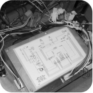
Attach the appropriate wiring diagram label. Ensure bottom of the diagram is towards the connectors.
-
Use wire ties to secure wires together. Keep the probe wires separate from the other wires.
-
Mount the panel to the front of the fryer using screws from the kit.
-
Enter special program mode and select the appropriate fryer type and unit is ready for use.
Related Content
Replacing the Indicator Lights
Replacing the Main Power Switch
RLink programming instructions
PFE 500/PFG 600 Hybrid Control Installation Instructions
PFE 500/PFG 600 Wi-Fi Verification and Troubleshooting Instructions
2nd Generation Radio for SMS: Hardware Installation
2nd Generation Radio for SMS: Software Update
FM08-748 2nd Generation Radio for SMS: Troubleshooting
Instructions for Fryer Control Replacement Kits
SMS 20 Auto Polish Programming Instructions
CFA PFE 500 Hybrid Wi-Fi Status Check
Troubleshooting the SMS 20 Control Countdown
Troubleshooting the SMS Control Online Projection System (OPS) Connection
Troubleshooting the Filter Count Not Reducing with Each Drop
Troubleshooting the PFE 500 and 561 E-41 Programming Settings Lost Error Code
Direct connect oil system operating instructions
4 Head PFE 500/ PFG 600 Removing the Lid
Pressure Assist Kit Installation
Temperature Probe Gauge Instructions
Replacing the Indicator Lights
Replacing the Main Power Switch
Installation of PFG 600 and PFG 600 SSI FM07-366 Electromechanical to C1000 Retrofit
PFG 600 SSI Electronic C1000 to C8000 Retrofit Kit
Hybrid Control and Wi-Fi Installation
Troubleshooting the SMS Control Online Projection System (OPS) Connection
Troubleshooting the PFG 600 E-41 Control Programming Lost Error Code
Direct connect retrofit PFG 600
Direct connect retrofit PFG-600
PFG 600 Ignition Module Retrofit Kit
PFG 600 SSI Fryers Gas Valve Replacement Kit
SAE Thread Filter Pump Installation
Pre VA SAE Thread Filter Pump Installation
Reference
PFE 500 and 561 Inspection and Planned Maintenance
PFE 500 KFC Annual Inspection Certification