Auxillary Buzzer Kit
Crosstip screwdriver
Kit number
14283
14284
14419
Estimated Time
30 Minutes
 | To avoid electrical shock or property damage, move the power switch to OFF and disconnect power. |
Remove electrical power to the unit.
Remove the two screws securing the control panel to the unit.
Lift panel up and out of unit, and slide the bottom of the panel in the slot, between the door frame and door to hold panel during installation of buzzer (Door may have to be slightly open).
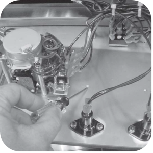
With a sharp pointed instrument, punch a hole out of the closest to the timer.
Turn panel over, and insert screw from kit into the hole.
Secure buzzer to the back of the panel with screw (Hole may need to be enlarged for screw).
Remove one of the wires on the 3rd position of the timer terminal block.
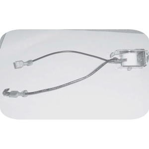
Attach this wire to the connector of one of the wires of the buzzer.
Attach connector back onto the 3rd position terminal of the timer.
Attach the remaining wire to the 1st terminal on the timer terminal block.
Mount panel back onto unit and return power. Unit is now ready for operation.
Related Content
Replacing the Indicator Lights
Replacing the Main Power Switch
Electronic C2000 Simple Control Retrofit Kit
RLink programming instructions
PFE 500/PFG 600 Hybrid Control Installation Instructions
PFE 500/PFG 600 Wi-Fi Verification and Troubleshooting Instructions
2nd Generation Radio for SMS: Hardware Installation
2nd Generation Radio for SMS: Software Update
FM08-748 2nd Generation Radio for SMS: Troubleshooting
Instructions for Fryer Control Replacement Kits
SMS 20 Auto Polish Programming Instructions
CFA PFE 500 Hybrid Wi-Fi Status Check
Troubleshooting the SMS 20 Control Countdown
Troubleshooting the SMS Control Online Projection System (OPS) Connection
Troubleshooting the Filter Count Not Reducing with Each Drop
Troubleshooting the PFE 500 and 561 E-41 Programming Settings Lost Error Code
Direct connect oil system operating instructions
4 Head PFE 500/ PFG 600 Removing the Lid
Pressure Assist Kit Installation
Temperature Probe Gauge Instructions
Replacing the Indicator Lights
Replacing the Main Power Switch
Installation of PFG 600 and PFG 600 SSI FM07-366 Electromechanical to C1000 Retrofit
PFG 600 SSI Electronic C1000 to C8000 Retrofit Kit
Hybrid Control and Wi-Fi Installation
Troubleshooting the SMS Control Online Projection System (OPS) Connection
Troubleshooting the PFG 600 E-41 Control Programming Lost Error Code
Direct connect retrofit PFG 600
Direct connect retrofit PFG-600
PFG 600 Ignition Module Retrofit Kit
PFG 600 SSI Fryers Gas Valve Replacement Kit
SAE Thread Filter Pump Installation
Pre VA SAE Thread Filter Pump Installation
Reference
PFE 500 and 561 Inspection and Planned Maintenance
PFE 500 KFC Annual Inspection Certification