Kit number
140585
140595
140609
140700
140701
140706
140686
Estimated Time
2 Hours

|
To avoid electrical shock or property damage, disconnect power before installing or servicing equipment.A qualified technician must perform the installation. |
-
Turn off power to the fryer.
-
Remove power cord from electrical supply.
-
Disconnect (by hand) the union between the oil return tube and pick-up tube inside the oil filter pan, located at front of fryer unit.
-
Use an adjustable wrench to loosen nut on the return tube located at the inlet side of pump.
-
Remove tube assembly.
-
Loosen nut on the supply tube (outlet side of pump) then loosen nut at the other end of supply tube.
-
Remove supply tube assembly. To disconnect conduit connector and electrical wires the access plate on the motor must first be removed.
-
Use a cross-tip head screwdriver to remove access plate from motor.
-
Loosen jam nut and remove conduit connector form pump / motor assembly.
-
Disconnect electrical wires from motor.
-
Unfasten mounting bolts and nuts.
-
Remove pump / motor assembly from mounting bracket in fryer unit.
-
Discard all used tube assemblies, bolts, nuts and washers.
-
If replacement pump is in the 12 o'clock position go to next step, otherwise continue with the following:
-
Loosen three internal hex set screws located between motor and pump body.
-
Rotate the pump to the 12 o'clock position. Ensure inlet port is pointed downard.
-
Tighten three internal hex screws securing the pump in the 12 o'clock position. Do not use a wrench to tighten jam nuts on 90° SAE fittings. Hand-tighten only, the jam nuts will be tightened in later steps.
-
-
Attach two 90° SAE fittings to pump.
-
Remove access plate from replacement pump / motor.
-
Wire the replacement pump the same way the previous pump was wire. For example if the previous pump was wired for 115V / 60 Hz AC power, then the replacement assembly must be wired 115V / 60 Hz AC.
-
Place the replacement pump / motor assembly onto mounting bracket.
-
Install conduit connector on pump / motor.
-
After conduit connector and wires are correctly installed, fasten access plate to motor.
-
Position all bolts along with washers (two per bolt) and nuts on the motor mount.
-
Finger-tighten fasteners to mounting bracket on fryer frame.
-
Install the new oil supply tube assembly between the outlet port of the pump and the inlet valve which is attached to the pot drain.
-
Hand-tighten each nut on the tube assembly.
-
Attach the new oil return tube assembly to the inlet port of the pump and hand-tighten the nut.
-
Assemble union to oil return tube.
-
Use an adjustable wrench to tighten the jam nut on each of the 90° SAE fittings.
-
Use an adjustable wrench to tighten each nut (Total of three) on both tube assemblies that were installed.
-
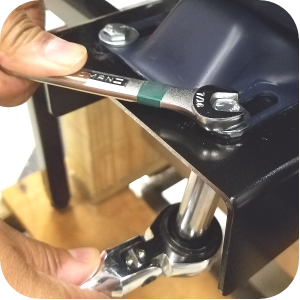
Tighten the pump / motor assembly to the mounting bracket on the fryer using a 7/16 in. wrench and 7/16 in. socket.
-
Hand-tighten the union between the return tube assembly and the pick-up tube in the filter pan.
-
Check all connections to ensure that none are lose.
-
Connect power cord to electrical supply and turn on power.
-
Ensure the vat is filled with oil.
-
Perform a filter. If oil does not pump it may be necessary to prime the pump.
-
While pump is running, check all connections for oil leaks.
-
If no leaks are observed, turn off pump. Installation is complete. If leaks are observed, turn off pump. Continue procedure.
-
Turn off power to fryer and disconnect power cord.
-
Tighten all connections where leaks were observed.
-
Connect power cord to electrical supply and turn on power.
-
Start filter pump and check for leaks. If no leaks are observed, installation is complete. If leak persists, turn off pump and contact technical support.
Related Content
PFG 600 Preventing Filter Pump Problems
Replacing the Filter Rinse Hose
Direct connect oil system operating instructions
Pre VA SAE Thread Filter Pump Installation
Troubleshooting the PFG 600 Oil Not Pumping Error Code
Troubleshooting the PFG 600 E-15 Drain Open Error Code
Electronic C2000 Simple Control Retrofit Kit
Installation of PFG 600 and PFG 600 SSI FM07-366 Electromechanical to C1000 Retrofit
PFG 600 SSI Electronic C1000 to C8000 Retrofit Kit
4 Head PFE 500/ PFG 600 Removing the Lid
RLink programming instructions
Pressure Assist Kit Installation
PFE 500/PFG 600 Wi-Fi Verification and Troubleshooting Instructions
PFE 500/PFG 600 Hybrid Control Installation Instructions
2nd Generation Radio for SMS: Hardware Installation
2nd Generation Radio for SMS: Software Update
FM08-748 2nd Generation Radio for SMS: Troubleshooting
Instructions for Fryer Control Replacement Kits
SMS 20 Auto Polish Programming Instructions
Temperature Probe Gauge Instructions
Direct connect retrofit PFG 600
Direct connect retrofit PFG-600
PFG 600 Ignition Module Retrofit Kit
PFG 600 SSI Fryers Gas Valve Replacement Kit
Hybrid Control and Wi-Fi Installation
Reference