PFG 600 SSI Electronic C1000 to C8000 Retrofit Kit
1/2 in. wrench
Crosstip head screwdriver
Flat-head screwdriver
Wire cutter or wire stripper
Kit number
140013
140014
Estimated Time
1 Hour
-
Drain oil from unit.
-
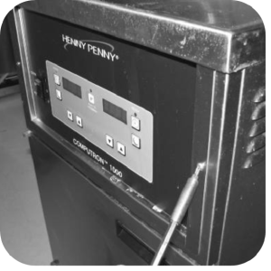
Remove the crosstip head screws from the control panel.
-
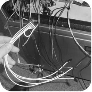
Remove wires to C1000 control panel and remove panel from unit.
-
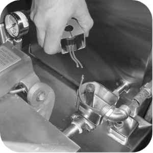
Remove pressure solenoid coil and install new solenoid coil from kit.
-
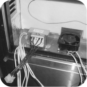
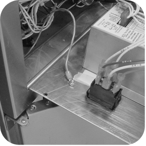
Locate transformer assembly and hardware in kit. Mount the transformer beside the fan.
-
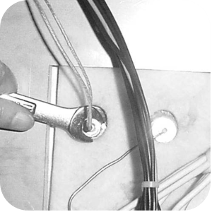
Use a 1/2 in. wrench to loosen the nut on probe compression fitting and remove probe and discard.
-
Place gauge against vat wall.
-
Push temperature probe through until it makes contact with the gauge.
-
Tighten temperature probe in place.
-
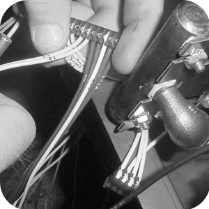
Locate the wire harness with the 6-pin red connector and connect the yellow wires to the high limit wires using wire nuts.
-
Connect the white wires to the drain switch wires using wire nuts.
-
Locate the wire harness with the 3-pin connector and connect L1 to wire going to pin #1 on connector.
-
Connect neutral to wire going to pin #3 on connector.
-
Locate the wire harness with the 12-pin connector and connect the pressure solenoid wires to P1 and P2 in positions 1 and 2 of the 12-pin connector using wire nuts.
-
Connect wires C, P and MV-1 in positions 3, 4 and 5 of the 12-pin connector to the gas valve wires.
-
Connect S1 and S2 in positions 6 and 7 of the 12-pin connector to the safety solenoid wires. If unit does not have a safety solenoid, individually cap off S1 and S2.
-
Connect wires MV, PV, TH and PV/MV in positions 9, 10, 11 and 12 of the 12-pin connector to ignition module.
-
Connect M1 and M2 wires to M1-1 and M2-1 pump motor wires.
-
Connect F1 and F2 to the fan wires FAN1 and FAN2.
-
Attach ground wire to stud on control panel.

-
Plug one 3-pin connector to the P1 connection onto the voltage conversion board. Plug another 3-pin connector onto the "power input" connection on the C8000 board.
-
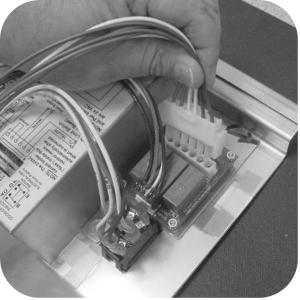
Plug all remaining connectors including the probe and new transformer harness into the back of the control.
-
The connector from the transformer can plug into two connectors on the control. Now the voltage can be selected, determine proper voltage and insert plug into the correct connector (208V. or 120/240V.).
-
Plug the 6-pin connector onto the connection on the voltage conversion board.
-
Wire tie the wires to keep them from interfering with the components.
-
Pull the wires to the left side of the controls, but do not bundle the power switch or probe wire with the others for ease of panel removal.
-
Secure the panel into place with screws previously removed.
-
Supply power to the fryer and unit is now ready for operation.
Related Content
Replacing the Indicator Lights
Replacing the Main Power Switch
Electronic C2000 Simple Control Retrofit Kit
Installation of PFG 600 and PFG 600 SSI FM07-366 Electromechanical to C1000 Retrofit
RLink programming instructions
PFE 500/PFG 600 Wi-Fi Verification and Troubleshooting Instructions
PFE 500/PFG 600 Hybrid Control Installation Instructions
2nd Generation Radio for SMS: Hardware Installation
2nd Generation Radio for SMS: Software Update
FM08-748 2nd Generation Radio for SMS: Troubleshooting
Instructions for Fryer Control Replacement Kits
SMS 20 Auto Polish Programming Instructions
Hybrid Control and Wi-Fi Installation
Troubleshooting the SMS 20 Control Countdown
Troubleshooting the SMS Control Online Projection System (OPS) Connection
Troubleshooting the PFG 600 E-41 Control Programming Lost Error Code
Direct connect oil system operating instructions
4 Head PFE 500/ PFG 600 Removing the Lid
Pressure Assist Kit Installation
Temperature Probe Gauge Instructions
Direct connect retrofit PFG 600
Direct connect retrofit PFG-600
PFG 600 Ignition Module Retrofit Kit
PFG 600 SSI Fryers Gas Valve Replacement Kit
SAE Thread Filter Pump Installation
Pre VA SAE Thread Filter Pump Installation
Reference