Cross-tip Screwdriver
Electric Drill
Drill bit
Kit number
140700
140701
140706
Estimated Time
25 Minutes
Purpose
Instructions on how to replace the existing PFG 600 control with a PFG hybrid control and install Wi-Fi on the fryer

|
To avoid electrical shock or property damage, move the power switch to OFF and disconnect power. |
-
Remove front existing control, and discard.
-
On the rear of the fryer, remove the junction box (J-Box) cover and set aside.
-
Remove the two screws holding the junction box to the frame. The junction box to the frame.
-
The junction box will need to shift to the right during Wi-Fi module install.
-
Position the Wi-Fi module / power supply on the rear of the fryer aligning the three holes on the bracket with the lower left part of the frame.
-
Position so the holes are near the middle of the frame tube and the Wi-Fi module doesn't overhang the tubing.
-
Use three #10 screws securing the Wi-Fi module and power supply assembly to the fryer.
-
Position the junction box as far right as possible, providing clearance away from the Wi-Fi module.
-
Secure the frame with two screws and then replace the cover.
-
The conduit connector(s) in the rear of the J-box may need to be rotated to assist in this movement.
-
Remove the right-side panel from the fryer.
-
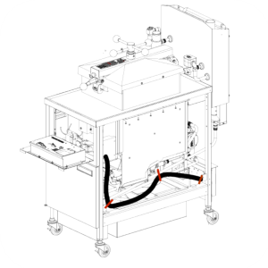
Route the Wi-Fi wire bundle along the side of the fryer, ensuring it's above the drain pan.
-
Route the harness underneath the Wi-Fi module, then up the back and along the side.
-
Route the end of the Wi-Fi wire bundle into the right front bottom corner of the component shroud.
-
Pull all slack in the wire bundle to the front of the fryer. Do not zip tie the Wi-Fi wire bundle to the power cord.
-
Use zip ties to secure the Wi-Fi wire bundle to the two (front and rear) metal brackets with holes on the side of the frame. Pull tight to remove slack.
-
Install a zip tie securing the Wi-Fi wire bundle in the middle of the fryer, to the condensate tube to hold the slack.
-
Slightly open the fryer door to provide temporary support for the control while connections are being made.
-
Hang the PFG hybrid control edge between the front shroud and the frame member to provide hands free access to the control (use the door for extra support).
-
Remove the existing 12-pin to 5-pin adapter wiring harness (white wires) and discard.
-
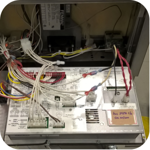
Obtain the new wiring harness, and then connect the new harness from the control’s 5-pin connector to the 12-pin wiring harness adapter.
-
Connect the common “COMW” wire with the red terminal, from the new harness, to the white wire with blue terminal, from the Wi-Fi bundle.
-
Connect the line “120W” wire with the red terminal, from the new harness, to the black wire with blue terminal, from the Wi-Fi bundle.
-
Connect the 4-pin connector and 2-pin connector coming from the Wi-Fi harness to the control.
-
Connect the remaining plugs and ground connection on the control.
-
Position the PFG hybrid control over the faceplate and install four screws securing the control.
Related Content
Replacing the Indicator Lights
Replacing the Main Power Switch
Electronic C2000 Simple Control Retrofit Kit
Installation of PFG 600 and PFG 600 SSI FM07-366 Electromechanical to C1000 Retrofit
PFG 600 SSI Electronic C1000 to C8000 Retrofit Kit
RLink programming instructions
PFE 500/PFG 600 Wi-Fi Verification and Troubleshooting Instructions
PFE 500/PFG 600 Hybrid Control Installation Instructions
2nd Generation Radio for SMS: Hardware Installation
2nd Generation Radio for SMS: Software Update
FM08-748 2nd Generation Radio for SMS: Troubleshooting
Instructions for Fryer Control Replacement Kits
SMS 20 Auto Polish Programming Instructions
Troubleshooting the SMS 20 Control Countdown
Troubleshooting the SMS Control Online Projection System (OPS) Connection
Troubleshooting the PFG 600 E-41 Control Programming Lost Error Code
Direct connect oil system operating instructions
4 Head PFE 500/ PFG 600 Removing the Lid
Pressure Assist Kit Installation
Temperature Probe Gauge Instructions
Direct connect retrofit PFG 600
Direct connect retrofit PFG-600
PFG 600 Ignition Module Retrofit Kit
PFG 600 SSI Fryers Gas Valve Replacement Kit
SAE Thread Filter Pump Installation
Pre VA SAE Thread Filter Pump Installation
Reference