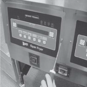
OFG 32X Open Drain Switch Retrofit
Crosstip screwdriver
Flat-head screwdriver
Pliers, Channel locks or Pipe wrench
3/8 in. Nutdriver or Socket
1 in. Wrench
1/2 in. Wrench
11/16 in. Wrench
Kit number
14682
Estimated Time
1 - 1.5 hours

|
To avoid personal injury or property damage, before starting this procedure, move the main power switch to the off position. Disconnect the main circuit breakers at the circuit breaker box or unplug service cord from wall receptacle. |
-
Remove electrical power supplied to the unit.
-
Drain oil from vat, ensure drains are in the closed position.
-
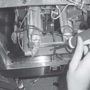
Open doors to filter pan and pull filter pan from fryer.
-
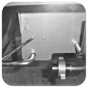
Using a crosstip screwdriver, remove the screws, and nuts. This secures the drain switch and cover. Discard cover.
-
Disconnect the wires to drain switch and discard old switch.
-
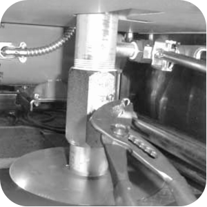
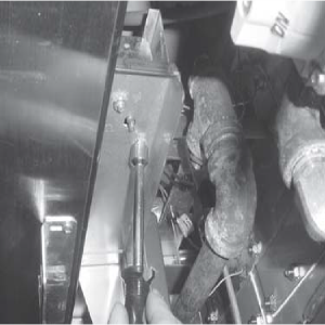
Use pliers or channel locks to remove the cotter pin securing the drain valve handle.
-
Use pliers or channel locks, remove the cotter pin securing the filter valve handle.
-
Pull the drain and filter valve handles from the bracket and discard the drain valve handle, but KEEP the filter valve handle.
-
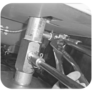
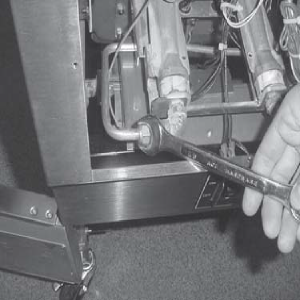
Use channel locks or a pipe wrench to unscrew the quick disconnect nipple from the tee fitting.
-
Pull the quick disconnect and nipple from the drain and filter rod bracket.
-
OPTIONAL: Remove right side panel if help is needed in unscrewing the nipple from the tee fitting.
-
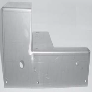
Use a crosstip screwdriver and remove all screws securing the drain and filter rod bracket. Remove and discard bracket.
-
Unplug all connectors from back of the control panel and remove from unit.
-
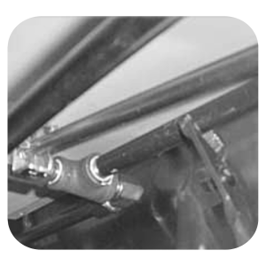
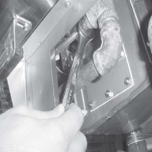
Use an 11/16 in. wrench to loosen the fitting of the left burner jet and pull tube from fitting.
-
Use an 11/16 in. wrench to loosen the fitting of the left burner jet and pull tube from the fitting.
-
Use a 11/16 in. wrench to loosen the lower burner jet fitting at the elbow and pull tube from elbow.
-
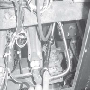
Use a 11/16 in. wrench to loosen the flexible burner tube at the fitting behind the high limit.

Ensure capillary bulb of high limit is located behind capillary bulb of thermostat. Both capillary bulbs and bulb holders should be positioned as not to interfere with basket or when cleaning the vat wall, or damage to capillary tube could result.
-
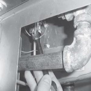
Use a 3/8 in. nutdriver or socket, remove the nuts securing the high limit bracket, and bracket.
-
Pull the high limit and bracket out.
-
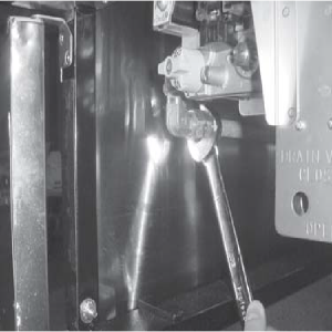
Use a 1 in. wrench to loosen the main gas line, to the left of the gas valve.
-
Use a 1/2 in. wrench to loosen the main gas line, to the left of the gas valve.
NOTICE -
To avoid product damage, do not drop or impact the pilot orifice. The burner will not operate without orifice.
-
Use a 1/2 in. wrench to loosen the pilot tube fitting. Lift up on the tube and remove the pilot orifice.
-
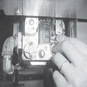
Label wires to the gas valve and remove wires from gas valve.
-
Use a crosstip screwdriver to remove the 3 screws securing the drain bracket to the frame. Remove bracket from unit.
-
Use a crosstip screwdriver to remove the two screws securing the gas valve to the bracket. Remove bracket from gas valve. Discard bracket.
-
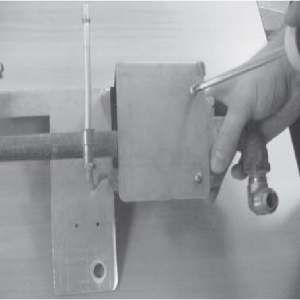
Mount gas valve to the drain rod bracket from the kit.
-
Push a black snap bushing into the hole. Mount the drain and filter rod bracket to the fryer, using screws provided in the kit.
-
Place pip sealant on the threads of the quick-disconnect nipple.
-
Slide the quick-disconnect nipple into the drain and filter rod bracket.
-
Connect quick-disconnect nipple into the tee fitting.
-
Connect the filter valve handle through the drain and filter rod bracket.
-
Connect the gas valve wires.
-
Connect gas line, burner jet tubes and pilot tube.
-
Connect high limit bracket, using the nuts provided in the kit.
-
Connect the control panel.
-
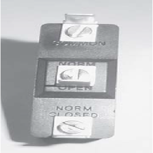
Use a flat-head screwdriver to remove and discard the "NORM CLOSED" terminal from the drain switch provided in the kit.
-
Connect the wires to the drain switch.
-
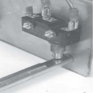
Mount drain switch and cover behind the drain rod bracket using nuts and screws provided in the kit.
-
Insert the new drain rod through the drain rod bracket and into the drain valve coupling. Push up on the plunger of the drain switch while inserting the drain rod handle, or damage to the drain switch may occur.
-
Position the handle so it is pointed to the left side of the unit with the drain valve closed.
-
Secure with a cotter pin from the kit. The plunger on the drain switch should be pressed by the drain rod when closed. When in the open position, the notch in the drain rod will release the drain switch plunger. A click should be heard indicating the switch is open.
NOTES: Ensure that the pilot orifice is installed when connecting the pilot tube.
Related Content
32X Direct Connect Oil System Operating Instructions
Direct Connect Retrofit Instructions
OFE 32X Open Drain Switch Retrofit Kit
OFG 322/323 Open drain switch retrofit kit instructions
OFE 32X Open Drain Switch Retrofit Kit
OGA-OFG 32X Ignition Module Retrofit
OFG/OGA 32X Replacing Gas Valve Kit
OFE 32X C1000 to C8000 Retrofit Kit
OFG 32X C1000 to C8000 Retrofit Kit
OFE 32X Installing the Spreader Bar
OFE 32X Reinforcing the Basket Rest
OFX 32X Replacing the Motor Shield
OFE 32X Installing the Filter Pump
OFE 32X Chick-Fil-A Element Bracket
OFE 32X Conversion from Full Pan to Single Pan
OGA-OFG 32X Replacing the Vacuum Switch
Reflashing the CFA ARM-Based Control
Reference