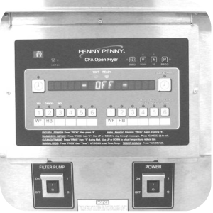
OFE 32X Installing the Spreader Bar
Crosstip Screwdriver
Flat-head Screwdriver
5/16" Wrench
1/4" Wrench
Kit number
140163
Estimated Time
1.5 Hours to 2 hours

|
Shock Hazard HIGH VOLTAGE PRESENT! To avoid personal injury, this procedure should only be performed by a service technician who is trained and understands electrical safety. |
-
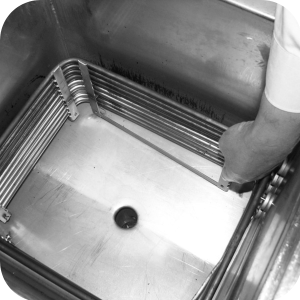
Drain oil into filter pan. Remove filter pan and fryer baskets from unit.
-
Ensure unit is unplugged and disconnected.
-
Remove four retaining screws with a 5/16" nut driver from the high limit bracket.
-
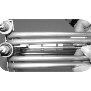
Pull the side locking bars from speakers.
-
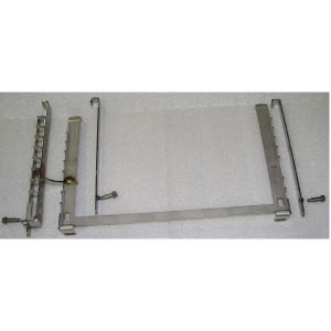
Remove the high limit bracket from between elements and remove bracket from high limit capillary bulb.
-
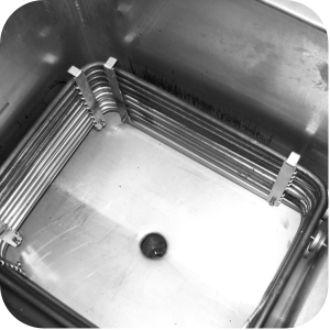
Remove the retaining screws with 5/16 in nut driver from both corner spreaders.
-
Pull locking bars from spreaders and remove spreaders from unit.
-
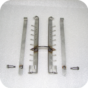
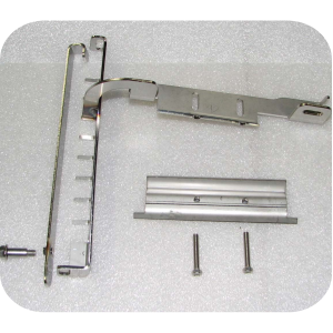
Locate the rear element spreader assembly supplied in the kit. Use a 5/16 in nut driver to remove 2 screws and 2 locking bars from assembly.
-
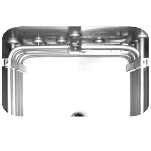
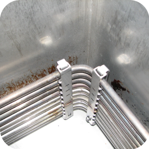
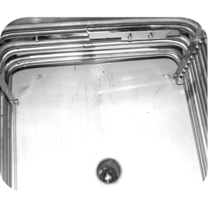
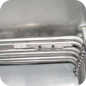
Position the corner element spreader assembly in the rear left corner. Ensure the top prong of spreader is under top element coil.
-
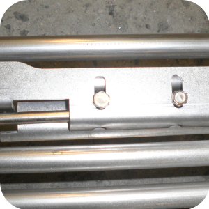
Install 2 locking bars in spreader assembly behind elements. Ensure the bar passes through the bottom and top slots, hooking into the notch of the spreader.
-
Thread screws into bottom of spreader and tighten with a 5/16 in socket & torque wrench to 30 in/lbs.
-
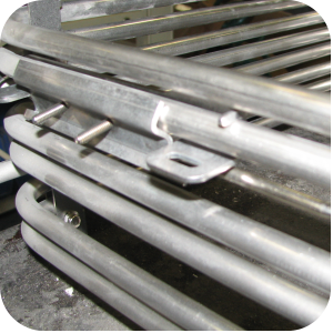
Locate the side element spreader assembly supplied in the kit. Use a 5/16" nut driver to remove the screws and 3 locking bars from assembly.
-
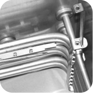
Place side bracket assembly on the right side of the elements.
-
Install the 3 side locking bars. Ensure each one passes through the bottom slots. Hook the bars in the top slot of each spreader. Push the spreader against elements so the locking bar engages the slots. Thread screws into bottom of spreader and tighten with a 5/16 in socket & torque wrench to 30 in/lbs.
-
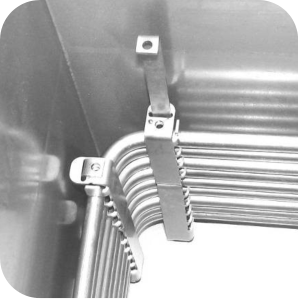
Locate the front high limit holder/spreader assembly supplied in the kit, along with the clamp and 2 screws. Use a 5/16 in nut driver to remove the screw from the locking bar.
-
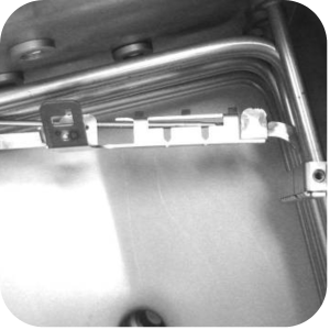
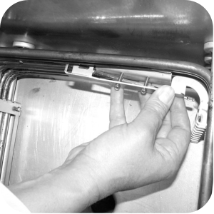
While the clamps are loose install the holder/spreader assembly. Slide high limit capillary bulb through bracket.
-
Slide bracket into place, with the high limit clamp between the second and third element coils.
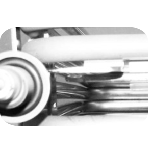
-
Ensure high limit bulb is completely through the bracket. Let about 1-1/14 in from bracket to bulb.
-
Install locking bar in spreader assembly behind corner of elements. Ensure the bar passes through the bottom slot and hook the top in the slot of spreader. Use 5/16 in socket and torque wrench, tighten locking bar screw to 30 in/lbs.
-
Use a 1/4 in socket and ratchet (or nut driver) to tighten the high limit clamp screws to 18 in/lbs.
-
Install fry basket support and fry basket.
-
Refill the vat with oil.
-
Plug the unit into the electrical outlet. Turn on the unit and check for normal operation.
-
Remove the temperature off-set in the controls.
-
To change drop detect removal and zero out loading time seconds, pess and hold the PROG button for one second. PROG should show in the display.
-
After 5 seconds, ENTER CODE scrolls through the display.
-
Enter code 5,1,3 and SELECT PROG PRODUCT now scrolls across the display.
-
Use 1-6 buttons, select the product.
-
Use the LEFT or RIGHT arrows, scroll over until DROP DETECT reads in display.
-
Use the UP or DOWN arrow to turn drop detect from YES to NO.
-
Press and release the PROG button one time to reach the LOADING TIME SECONDS. Use the DOWN button to set the loading time to 0 seconds.
-
Press and release the PROG button two times to return to the SELECT PROG PRODUCT step.
-
When done with changes to both products, press and hold the PROG button to exit programming mode.
-
For Offset Adjustment Procedure, press and hold the PROG button at the top right of the control panel for 6 seconds, or until the second sound, then release. Level 2 should appear on the screen.
-
Press the left arrow at the top right of the panel twice until the word TECH appears.
-
Enter code 1 1 2 2 1 1 2 2 using men keys to enter TECH MODE.
-
Press the right arrow button until you get to step T-9 POT TEMP - - CALIB/OFFSET/HIGHEST.
-
Press and hold the #2 menu button, this will display the current offset adjustment.
-
Continue holding the #2 button while pressing the up arrow till the offset reads 0.
-
Release both buttons.
-
Simultaneously press the INFO and PROG buttons at the top right of the panel to exit proramming.
-
Press and release the PROG button at the top right of the control panel.
-
Immediately press and release the #4 button (labeled diagnostics).
-
The display will ask "Is color o.k.?".
-
Answer "No" by pressing #3 (Labeled "No").
-
Use the right or left arrow at the top right of the control to adjust the product as needed.
-
Press #2 also marked "Cancel" to return to normal operation.
NOTE: Do not use a power driver to remove or install screws from the assemblies in kit. Use only hand tools or damage to the screw threads could result.
NOTE: To fine tune this, cook a large batch of Waffle Fries to procedure. If fries are too crispy or soggy, the adjustment can be fine tuned using the "Diagnostics color adjustment" feature.
Related Content
Replacing the Blower Motor Assembly
Replacing Heating Contactors (Electric Only)
Replacing Heating Elements (Electric Only)
Replacing the High Limit Temperature Control (Electric Units)
Replacing the High Temperature Limit Control (Gas Units)
Replacing the Flame Sensor (Gas Units)
Replacing the Pilot / Ignitor Assembly
Replacing the Gas Control Valve Assembly
Replacing the Temperature Probe
OGA-OFG 32X Ignition Module Retrofit
OFG/OGA 32X Replacing Gas Valve Kit
OFE 32X Chick-Fil-A Element Bracket
Troubleshooting the OFG 32X Fryer Stuck in Ignition Loop
Troubleshooting the OFG 32X Fryer E-4 Control Overheating Error Code
Troubleshooting the OFE and OFG 32X Fryer E-5 Oil Overheating Error Code
Troubleshooting the OFE and OFG 32X Fryer E-6 Temperature Probe Error Code
Troubleshooting the OFE and OFG 32X Fryer E-10 High Limit Error Code
Troubleshooting the OFE and OFG 32X Fryer E-20A Fan Sensor Stuck Closed Error Code
Troubleshooting the OFG 32X Fryer E-20B Pressure Switch Stuck Error Code
Troubleshooting the OFG 32X Fryer E-20D Ignition Failure Error Code
Troubleshooting the OFE 32X Fryer E-26 Heat Amps Locked Error Code
Troubleshooting the OFE and OFG 32X Fryer E-92 24V Circuit Overload Error Code
Troubleshooting the OFE 32X Fryer W-1 Low Voltage Warning
Troubleshooting the OFE 32X Fryer W-2 Slow Heating Warning
Troubleshooting the OFE 32X Fryer W-3 Was Not Ready Warning
Troubleshooting the OFE 32X Fryer W-4 Slow Cooking Warning
Troubleshooting the OFE 32X Fryer W-5 Slow Cooking Warning
Troubleshooting the OFE 32X Fryer W-6 Slow Cooking Warning
Troubleshooting the OFE 32X Fryer W-7 Low Amps Warning
Troubleshooting the OFE 32X Fryer W-9 Discard Product Warning
32X Direct Connect Oil System Operating Instructions
Direct Connect Retrofit Instructions
OFE 32X Open Drain Switch Retrofit Kit
OFG 322/323 Open drain switch retrofit kit instructions
OFE 32X Open Drain Switch Retrofit Kit
OFG 32X Open Drain Switch Retrofit
OFE 32X C1000 to C8000 Retrofit Kit
OFG 32X C1000 to C8000 Retrofit Kit
OFE 32X Reinforcing the Basket Rest
OFX 32X Replacing the Motor Shield
OFE 32X Installing the Filter Pump
OFE 32X Conversion from Full Pan to Single Pan
OGA-OFG 32X Replacing the Vacuum Switch
Reflashing the CFA ARM-Based Control
Reference