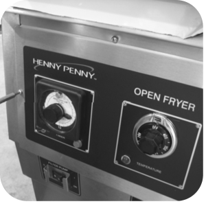
OFE 32X Electronic Retrofit
Crosstip screwdriver
Wire Cutter/Stripper
Utility knife
Adjustable Wrench
11/16" in. Socket
Ratchet and Extension
Pipe thread sealant
Kit number
14940
-
Drain oil from fryer.
-
Remove the crosstip screws from the control panel.
-
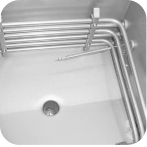
Remove thermostat bulb and capillary from bracket in vat.
-
Use an 11/16 in. socket to remove fitting from inside control area and pull thermostat from bulb and capillary.
-
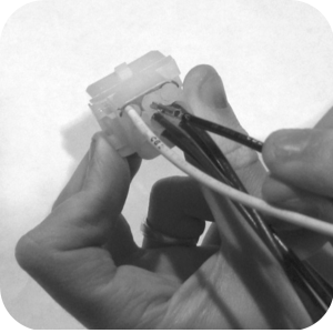
Disconnect the 9-pin connector and pull the control panel assembly from the unit.
-
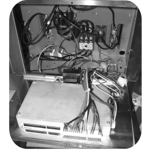
Remove contactor coil wires 4, 5, 6, and 20 from both contactors. Leave the circuit breaker or fuse wires if present.
-
Remove drain switch and high limit wires.
-
Disconnect any remaining wires to the 9-pin connector in control area and remove 9-pin connector.
-
Disconnect any remaining wires to the 5-pin connector in control area and remove 5-pin connector.
-
Remove any remaining power switch wires.
-
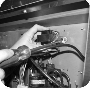
Remove transformer.
-
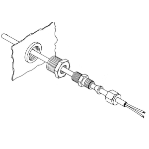
Locate 3 in probe from kit and install new temperature probe.
-
Locate 9-pin connector harness and wire # CB2 in kit. Insert CB2 into position 4 on the 9-pin connector (to the right of CB1). For units different than 208 volts please use position # 7.
-
If circuit breakers or fuses are present, connect wires CB1 and CB2 to the circuit breakers or fuses, along with wires 71 and 72 using the 2-bladed terminals in kit.
-
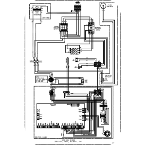
Connect remaining wires of 9-pin connector to power switch. Reference wiring diagrams.
-
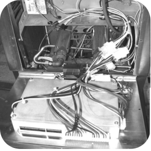
Locate 15-pin connector harness in kit. Connect wires H1 and H2 to the heat contactor coil, and connect wires S1 and S2 to primary contactor coil.
-
Connect wires HL1 and HL2 to the high limit and connect wires DS1 and DS2 to the drain switch.
-
Locate transformer and nuts in kit and mount on control panel.
-
Locate connector harness in kit and attach them to the control. Attach transformer connector.
-
Use wire tires to secure wires together. Keep probe wires separate from the other wires and do not bundle the high voltage wires with the control wires.
-
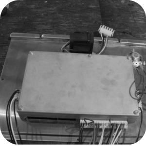
Instal new control panel to front of fryer, secure with screws previously removed. Restore power to unit.
-
Enter special program mode and select appropriate fryer type.
Related Content
Replacing the Complete Control Panel
Replacing the I/O Power Supply Board Assembly
Replacing the Speak Assembly (Gas Units)
Replacing the Speaker Assembly (Electric Units)
OFE 32X C1000 to C8000 Retrofit Kit
OFG 32X C1000 to C8000 Retrofit Kit
Troubleshooting an Unresponsive Control Displaying 8's
OGA-OFG 32X Replacing the Vacuum Switch
Troubleshooting the OFE and OFG 32X Fryer E-41 System Data Lost Error Code
32X Direct Connect Oil System Operating Instructions
Direct Connect Retrofit Instructions
OFE 32X Open Drain Switch Retrofit Kit
OFG 322/323 Open drain switch retrofit kit instructions
OFE 32X Open Drain Switch Retrofit Kit
OFG 32X Open Drain Switch Retrofit
OGA-OFG 32X Ignition Module Retrofit
OFG/OGA 32X Replacing Gas Valve Kit
OFE 32X Installing the Spreader Bar
OFE 32X Reinforcing the Basket Rest
OFX 32X Replacing the Motor Shield
OFE 32X Installing the Filter Pump
OFE 32X Chick-Fil-A Element Bracket
OFE 32X Conversion from Full Pan to Single Pan
Reflashing the CFA ARM-Based Control
Reference