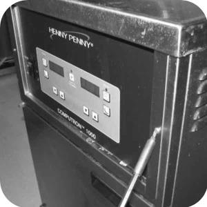
OFE 32X C1000 to C8000 Retrofit Kit
Flat-Head Screwdriver
Crosstip Screwdriver
1/2 in Wrench
Wire Cutter/Stripper
Kit number
140072
140073
Estimated Time
1 Hour to 1.5 hours
-
Drain oil into filter pan.
-
Use a crosstip screwdriver to remove screws from the control panel.
-
Remove wires to C1000 control panel and remove panel from unit.
-
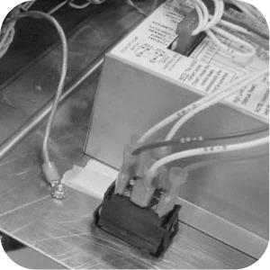
Remove transformer from the C1000 controls and attach it to the studs on the mounting bracket provided in the it. Use existing nuts.
-
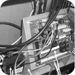
For Full Vat Fryers connect transformer to either P2 (240V) or P3 (208V) connector on I/O board.
-
For Split Vat Fryers connect transformer to either P7 (240V) or P8 (208V) connector on I/O board.
-
Attach mounting bracket to frame using screws from kit.
-
For Split Vat Fryers locate 12-pin wire harness in kit with wires labeled as follow: CB1, CB2, RPS1, RPS2, RPS3, RPS4, LPS1, LPS2, LPS3, LPS4.
-
Attach wires to circuit breakers, and right and left heater switches. Refer to wiring diagrams 81046 or 81047, provided in the kit.
-
Locate C8000 controls in kit and connect 12-pin connector to I/O board.
-
Connect 4-pin connector from C8000 controls to probe wires.
-
Connect 14-pin and 4-pin connectors from C8000 controls to I/O board.
-
Connect 15-pin (right and left for split vats) and 12-pin connectors from I/O board to fryer.
-
Connect speaker wires to C8000 control.
-
Attach ground wire to stud on control panel.
-
Wire tie the wires to keep them from interfering with other components. Pull wires to the left side of controls. Do not bundle the power switch or probe with other wires, doing this will increase ease of panel removal.
-
Secure C8000 control panel into place with new screws provided in kit.
-
Replace wiring diagrams on fryer with diagrams from kit.
-
Supply power to the fryer and unit is operational. Refer to 12 button controls.

|
To avoid personal injury or property damage, before starting this procedure, move the main power switch to the off position. Disconnect the main circuit breakers at the circuit breaker box or unplug service cord from wall receptacle. |
| Shock Hazard HIGH VOLTAGE PRESENT! To avoid personal injury, this procedure should only be performed by a service technician who is trained and understands electrical safety. |
Note: Electric open fryers made before serial #BA0908015 will require a 9-pin to 12-pin power adaptor harness from kit.
For Full:
78453 with 81161, 78078 with 81162, and 79098 with 82329.
For Split:
78453 with 81046, and 78078 with 81047
Related Content
Replacing the Complete Control Panel
Replacing the I/O Power Supply Board Assembly
Replacing the Speak Assembly (Gas Units)
Replacing the Speaker Assembly (Electric Units)
OFG 32X C1000 to C8000 Retrofit Kit
Troubleshooting an Unresponsive Control Displaying 8's
OGA-OFG 32X Replacing the Vacuum Switch
Troubleshooting the OFE and OFG 32X Fryer E-41 System Data Lost Error Code
32X Direct Connect Oil System Operating Instructions
Direct Connect Retrofit Instructions
OFE 32X Open Drain Switch Retrofit Kit
OFG 322/323 Open drain switch retrofit kit instructions
OFE 32X Open Drain Switch Retrofit Kit
OFG 32X Open Drain Switch Retrofit
OGA-OFG 32X Ignition Module Retrofit
OFG/OGA 32X Replacing Gas Valve Kit
OFE 32X Installing the Spreader Bar
OFE 32X Reinforcing the Basket Rest
OFX 32X Replacing the Motor Shield
OFE 32X Installing the Filter Pump
OFE 32X Chick-Fil-A Element Bracket
OFE 32X Conversion from Full Pan to Single Pan
Reflashing the CFA ARM-Based Control
Reference