OFE 32X Chick-Fil-A Element Bracket
1/4 in. Nut Driver
5/16 in. Nut Driver
1 in/lbs Torque Wrench
Kit number
140634
Estimated Time
30 minutes

|
To avoid electrical shock or property damage, move the power switch to OFF and disconnect power. |
|
|
Only perform this procedure when the unit is cool or severe burns may result. |
-
Drain the oil from the vat.
-
Remove the fry basket and the fry basket support.
-
Disconnect the unit by unplugging from the electrical outlet or circuit breaker.
-
Allow the fryer to cool before beginning work.
-
A breaker lockout device is recommended. If disconnecting the fryer from a hard wire connection disconnect the cord at the fryer, not the wall junction box. Tape, or safe-off exposed conductors on the wire/cord.
-
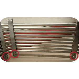
On the right side of the element, remove the three retaining screws with a 5/16 in nut driver, and then remove the right-side locking bar and bracket.
-
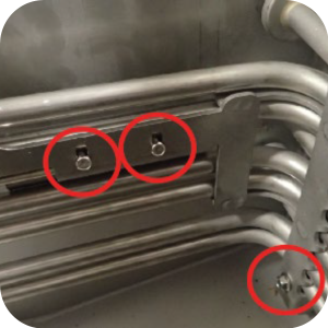
On the left front-side of the element, remove two retaining screws with a 1/4 in. nut driver, and then remove the hi-limit probe clamp.
-
On the left front-side of the element, remove one retaining screw with 5/16 in nut driver and then remove the left front-left side locking bark and bracket.
-
On the left-rear corner of the element, remove the two retaining screws with a 5/16 in nut driver and then remove the left-rear-corner locking bar and bracket.
-
Locate the assemblies from the kit and if recieved preassembled, usea 5/16 in nut driver to remove the shoulder bolts and locking bars from the brackets. Refer to the Components section.
-
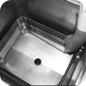
Place the right side bracket assembly on the right side (inside) of the elements.
-
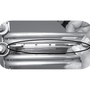
Install the three side locking bars, ensuring each one passes through the bottom slot and hooks into the top slot of each bracket.
-
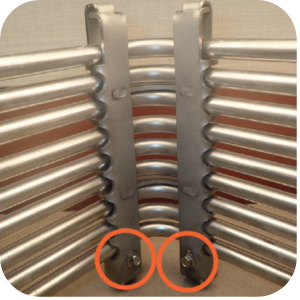
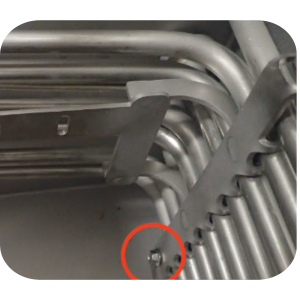
Thread shoulder bolts through the bracket into the locking bar and tighten with a 5/16 in socket and torque wrench to 35 in/lbs.
-
Place the left rear-side bracket assembly on the left side (inside) of the elements.
-
Install the two side locking bars on the rear corner, ensure each one passes through the bottom slots and hook into the top slot of each bracket.
-
Thread shoulder bolts through the bracket into the locking bar and tighten with a 5/16 in socket and torque wrench to 35 in/lbs.
-
Install the left-front (high temperature limit probe) bracket and locking bar with one shoulder bolt and tighten with a 5/16 in socket and torque wrench to 35 in/lbs.
-
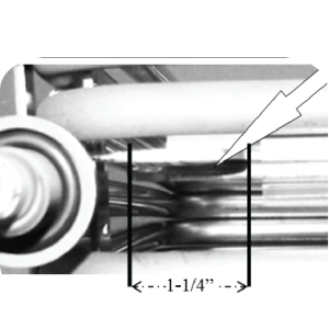
Safely place the high temperature limit probe against the vat side of the bracket.
-
Note: Ensure the high limit bulb is completely through the bracket, showing about 1-1/4 in. from bracket to the tip of the bulb. High limit probs are sensitive to the amount of exposure.
-
Clamp in place with plate and two bolts.
-
Tighten with a 1/4 in socket and torque to 18 in/lbs do not overtighten or damage to the probe may result.
Note: If necessary, squeeze the locking bar and bracket together at the bottom. Ensure the locking bars hook in both the top and bottom slots of the element brackets.
Note: If necessary, squeeze the locking bar and bracket together at the bottom. Ensure the locking bars hook in both the top and bottom slots of the element brackets.
Related Content
Replacing the Blower Motor Assembly
Replacing Heating Contactors (Electric Only)
Replacing Heating Elements (Electric Only)
Replacing the High Limit Temperature Control (Electric Units)
Replacing the High Temperature Limit Control (Gas Units)
Replacing the Flame Sensor (Gas Units)
Replacing the Pilot / Ignitor Assembly
Replacing the Gas Control Valve Assembly
Replacing the Temperature Probe
OGA-OFG 32X Ignition Module Retrofit
OFG/OGA 32X Replacing Gas Valve Kit
OFE 32X Installing the Spreader Bar
Troubleshooting the OFG 32X Fryer Stuck in Ignition Loop
Troubleshooting the OFG 32X Fryer E-4 Control Overheating Error Code
Troubleshooting the OFE and OFG 32X Fryer E-5 Oil Overheating Error Code
Troubleshooting the OFE and OFG 32X Fryer E-6 Temperature Probe Error Code
Troubleshooting the OFE and OFG 32X Fryer E-10 High Limit Error Code
Troubleshooting the OFE and OFG 32X Fryer E-20A Fan Sensor Stuck Closed Error Code
Troubleshooting the OFG 32X Fryer E-20B Pressure Switch Stuck Error Code
Troubleshooting the OFG 32X Fryer E-20D Ignition Failure Error Code
Troubleshooting the OFE 32X Fryer E-26 Heat Amps Locked Error Code
Troubleshooting the OFE and OFG 32X Fryer E-92 24V Circuit Overload Error Code
Troubleshooting the OFE 32X Fryer W-1 Low Voltage Warning
Troubleshooting the OFE 32X Fryer W-2 Slow Heating Warning
Troubleshooting the OFE 32X Fryer W-3 Was Not Ready Warning
Troubleshooting the OFE 32X Fryer W-4 Slow Cooking Warning
Troubleshooting the OFE 32X Fryer W-5 Slow Cooking Warning
Troubleshooting the OFE 32X Fryer W-6 Slow Cooking Warning
Troubleshooting the OFE 32X Fryer W-7 Low Amps Warning
Troubleshooting the OFE 32X Fryer W-9 Discard Product Warning
32X Direct Connect Oil System Operating Instructions
Direct Connect Retrofit Instructions
OFE 32X Open Drain Switch Retrofit Kit
OFG 322/323 Open drain switch retrofit kit instructions
OFE 32X Open Drain Switch Retrofit Kit
OFG 32X Open Drain Switch Retrofit
OFE 32X C1000 to C8000 Retrofit Kit
OFG 32X C1000 to C8000 Retrofit Kit
OFE 32X Reinforcing the Basket Rest
OFX 32X Replacing the Motor Shield
OFE 32X Installing the Filter Pump
OFE 32X Conversion from Full Pan to Single Pan
OGA-OFG 32X Replacing the Vacuum Switch
Reflashing the CFA ARM-Based Control
Reference