Lid Handle Replacement Instructions
5/32 in. Hex key
5/32 in. Hex key socket,
Extended length crosstip head screwdriver
Flathead screwdriver
Loctite #271 Red high strength threadlocker
Ratchet and 10 in. extension
Torque wrench
Kit number
140648
Estimated Time
30 Minutes

|
Only perform this procedure when the unit is cool or severe burns may result. |

|
To avoid severe burns, do not open the drain valve while vat is under pressure. Allow the pressure to reduce to atmospheric pressure. |
|
|
To avoid serious personal injury:
|
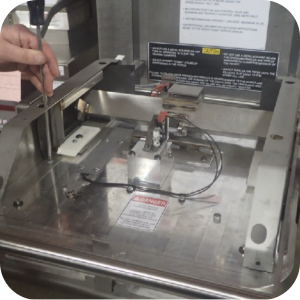
Removing the Lid Handle Shaft and Linkage
-
Engage the front lid latch.
-
Use a crosstip head screwdriver to remove two screws in rear of lid top cover.
-
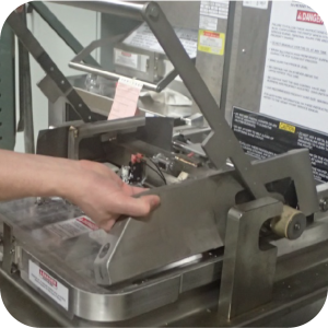
Use a flathead screwdriver to pry rear of lid top cover up.
-
Pull lid top cover up until it clears sides.
-
Use a flathead screwdriver to pry front of the lid cover forward until it clears the two front pins.
-
Remove lid top cover and set aside.
-
Use a crosshead screwdriver to remove 3 screws on each side of lid sides.
-
Lift and hold handle with one hand as you lift and turn the lid side cover to remove it. Repeat for the other side cover and set both lid sides aside.
-
Remove and discard both cam slide fillers.
-
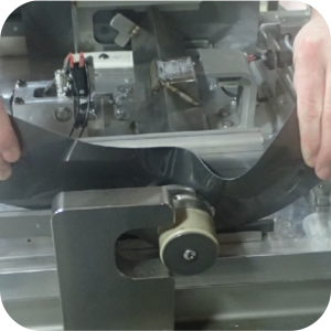
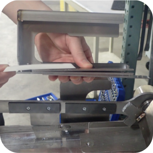
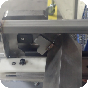
Use a 5/32 in. hex key to remove the two screws and split ring lockwashers on the cam guide assembly on each side of the lid. Using a hex key with well-defined edges can assist in removing the screws.
-
Lift the lid handle and linkage assembly while sliding out the cam guide assembly. Keep the cam guide assembly together to save time during re-installation.
-
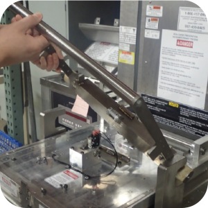
Push lid handle and linkage assembly towards rear of fryer and lift to remove from lid.
Installing the Lid Handle Shaft and Linkage
-
Prepare to install the lid handle shaft and linkage

-
Install new lid handle and linkage assembly by sliding it between hook latches.
-
Lift lid handle and linkage assembly and slide cam guide assembly under it.
-
Ensure holes in all pressure pads, shims and spacers align with holes in lid.
-
Apply blue threadlocker to both screws and lid holes.
-
Start threading through cam guide assembly.
-
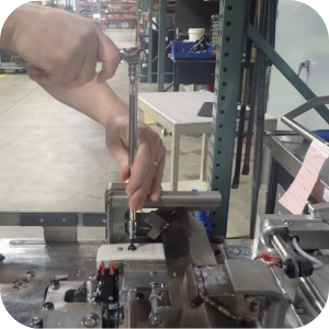
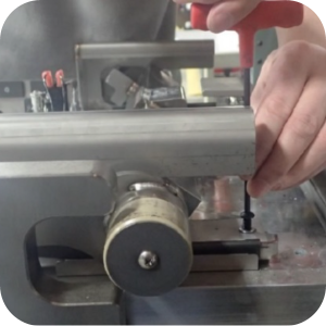
Use a 5/32 in. hex key to tighten both screws.
-
Torque screws to 96 in/lb.
-
Apply spindle lube to interlock latch pin.
-
Pull lid handle and linkage assembly forward and down to engage lid lock.
-
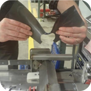
Install new cam slide filler over lid arm assembly. When replacing cam slide fillers, bend 4 outside corners of new fillers to 45 degree angle towards lid. Long side should be towards front of fryer. Ensure the front and back of the slide filler engages.
-
Pull lid handle and linkage assembly up to disengage lid lock.
-
Replace lid side cover.
-
Apply blue threadlocker to the threads of each side cover screw and lid holes.
-
Use a crosshead screwdriver to install 3 screws through each side cover into the lid.
-
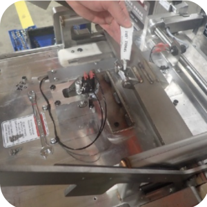
Use a permanent marker to write the serial number on the lid handle.
-
Take a photograph of replaced lid handle and submit with warranty claim.
-
Pull handle down and forward to engage latch. Repeat several times to ensure lid handle and linkage assembly is correctly installed.
-
Ensure holes in front of lid cover are aligned with front pegs and place on top of assembly.
-
Install two screws in rear of lid cover.
Inspecting the Gasket Screws
-
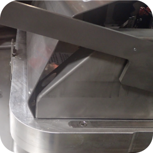
Raise and tilt the lid upward.
-
Cover the vat with a full sheet pan to avoid contamination of oil.
-
Inspect and tighten all 16 lid gasket retainer screws around perimeter of lid gasket to 18 in. lb. Do not over tighten or screws may break.
-
If any lid gasket retainer screws are missing. Apply threadlocker and install using provided screws. Tighten screws to gasket retainer to 18. / lb. Do not overtighten or screws may break.
-
If any lid gasket retainer screws are broken, submit photographs of broken screws and serial number to pxecheck@hennypenny.com to receive further instruction. The lid will be evaluated to determine if a replacement is necessary.
-
Pull back the lid gasket and inspect all 12 lid liner screws. If any screws are missing, broken or etc. do the same as previous step.
-
Save any unused screws for potential use at next inspection.
-
Customer may resume normal use of fryer.
-
Related Content
Replacing the Nylatron Vertical Strip
Converting Velocity Pressure Fryer to Open Fryer
Armored Cable Grounding Installation Instructions for Australia
Lid Latch Adjustment or Replacement
Velocity Steam Box Swap-out Instructions
Velocity Nylatron Vertical Filler Strips Installation Instructions
Velocity Deadweight Orifice Clean-out Tool Installation and Maintenance
Velocity Lid Cable Replacement
Add pressure gauge to PXE unit Instructions (Japan / Hong Kong)
Instructions to replace PXE Interlock Latch Pivot Pin
Add pressure gauge to PXE unit Instructions
Troubleshooting a PXE 100 E-84 Error Code
Troubleshooting a PXE 100 E-13 Error Code
ZigBee Radio Communication Kit
Selector Valve Motor/Encoder Replacement
Front Dispose Addition (for Bulk Oil Units)
Remove Selector Valve to ATO flex tube
Temp/Level Probe Fitting Replacement
Label Replacement Instructions
High Limit Protection Probe Installation (CE Version built prior to 5/2020, ALL Versions after)
High Limit Protection Probe Installation (UL Version built prior to 5/2020)
Menu Card Removal Replacement Instructions
Save and Load Setpoint Instructions
Flexible Line Replacement Kit (Formed Tube), (Standard, Bulk-Oil Fryer)
Flexible Line Replacement Kit (Formed Tube), (Standard, NON Bulk-Oil Fryer)
Velocity High Limit Adjustment Instructions
Reference
Product Racking Recommendations
PXE 100 Inspection and Planned Maintenance