Velocity Deadweight Orifice Clean-out Tool Installation and Maintenance
Drill gun with crosstip head bit
Kit number
140622
Estimated Time
5 Minutes

|
To avoid electrical shock or property damage, move the power switch to OFF and disconnect power. |

|
To avoid severe burns, do not remove deadweight cap while operating fryer. |
Purpose
The weight carriage on the rear of the fryer counter-balances the lid system for easier operation. Two cables attached to it; the safety cable on the left-side and the lifting cable in the middle. The lifting cable tension should be tight and the safety cable tension should be loose enough that when squeezing the cable together, the two sides can touch. Both cables should be replaced in pairs. The white label denotes the cable replacement date and should be affixed to the back of the fryer's frame.
-
Locate a 3/8 in. nut driver.
-
Turn off fryer and allow to cool.
-
Disconnect power.
-
Move unit away from obstructions. Ensure there is room to install and use the tool needed.
-
Remove screws and P-clips from bag.
-
Insert screws through hole in P-clips.
-
Use a drill gun to run each screw into the sheet metal on the rear shroud.
-
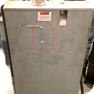
The holes must be drilled about 10 in. down from the top shroud, and in line with the steam stack behind the internal exhaust tube and deadweight box. If positioned too far the screws could damage the vertical lid slides, or if positioned too low, the counterbalance weights may impact the screws.
-
Align P-clips so that the clean-out tool can pass through each and stay affixed to rear of unit.
-
Return fryer to service.
Maintenance
The deadweight cleaning tool is used to breakup and remove debris from the deadweight orifice and deadweight tubing. Clean the deadweight orifice by performing the following procedure after any cook cycle where an E-14 PRESSURE TOO HIGH error is displayed, and every 30 days when removing the deadweight for cleaning.
-
To clean out orifice do the following:
-
Remove the orifice cleaning tool from rear of the fryer.
-
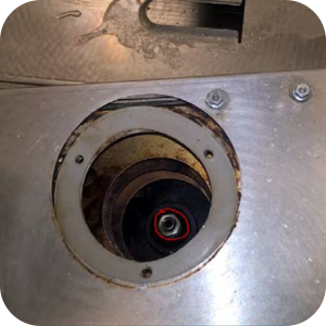
Remove the steam stack (exhaust tube) from the top of the fryer by loosening the three thumb screws until it can be lifted up and off the top shroud. The deadweight inside the steam stack is not captive and can fall out of the steam stack if tipped.
-
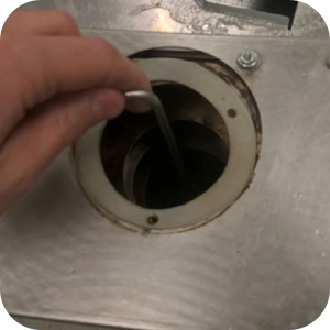
Insert the tool into the orifice and plunge up and down several times as far as the tool can reach.
-
Install steam stack with deadweight and return tool to rear of fryer.
-
Related Content
Replacing the Filter Pump Motor
Replacing the Filter Pump Motor Seal
Replacing the Filter Pump Motor Rollers
Replacing the Selector Valve Motor and Encoder
Replacing the Drain Valve and Actuator
Replacing the Nylatron Vertical Strip
Velocity Nylatron Vertical Filler Strips Installation Instructions
Selector Valve Motor/Encoder Replacement
Velocity Lid Cable Replacement
Instructions to replace PXE Interlock Latch Pivot Pin
Front Dispose Addition (for Bulk Oil Units)
Remove Selector Valve to ATO flex tube
Flexible Line Replacement Kit (Formed Tube), (Standard, Bulk-Oil Fryer)
Flexible Line Replacement Kit (Formed Tube), (Standard, NON Bulk-Oil Fryer)
Troubleshooting Slow Refill No Detect Error on OXE 100
Troubleshooting Bulk Tank Full Message on OXE 100
OXE 100 Troubleshooting the E-18 Level Probe Failure Error Code
OXE 100 Troubleshooting the Oil Not Pumping
Lid Latch Adjustment or Replacement
Armored Cable Grounding Installation Instructions for Australia
ZigBee Radio Communication Kit
Temp/Level Probe Fitting Replacement
Label Replacement Instructions
High Limit Protection Probe Installation (CE Version built prior to 5/2020, ALL Versions after)
High Limit Protection Probe Installation (UL Version built prior to 5/2020)
Menu Card Removal Replacement Instructions
Save and Load Setpoint Instructions
Velocity High Limit Adjustment Instructions
Replacing the Nylatron Vertical Strip
Converting Velocity Pressure Fryer to Open Fryer
Velocity Steam Box Swap-out Instructions
Lid Handle Replacement Instructions
Add pressure gauge to PXE unit Instructions (Japan / Hong Kong)
Add pressure gauge to PXE unit Instructions
Troubleshooting a PXE 100 E-84 Error Code
Troubleshooting a PXE 100 E-13 Error Code
Reference
Product Racking Recommendations
OXE 100 KFC Annual Inspection Certification
Product Racking Recommendations