Front Dispose Addition (for Bulk Oil Units)
Adjustable wrench
Crosstip head screwdriver
Drill gun with 5/16 in. bit
Flathead screwdriver
Pipe wrench
Thread sealant
Kit number
140597
Estimated Time
60 minutes

|
To avoid electrical shock or property damage, move the power switch to OFF and disconnect power. |
-
Disconnect fryer electrical power.
-
Use a crosstip head screwdriver to remove left side panel.
-
Remove condensate tank, ATO tank, and filter pan.
-
Place pan or towel under ATO oil connection female PNP area.
-
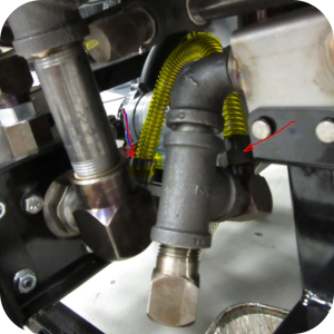
Remove 10 in. flex tube that connects selector Valve and ATO manifold, discard.
-
Loosen lock nut on selector valve elbow fitting.
-
Position the fitting facing toward front of the fryer, remain loose until flex line connection is made.
-
Disconnect one side of 18 in. flex tube at ATO manifold, ensure not to bend sharply.
-
Remove ATO manifold and female PNP connection from fryer.
-
Use a flathead screwdriver to push in small teeth in pins to remove pins.
-
Remove the female PNP connection from manifold, discard manifold fittings.
-
Install fitting into ATO connection, use food grade thread sealant on threads.
-
Re-isntall ATO connection back to fryer using toothed pins.
-
Connect loose end of 18 in. flex tube to ATO connection and tighten.
-
Ensure the tube has no kinks, keep radius larger than golf ball size, and no bends within a few inches of fitting.
-
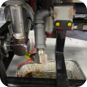
Assemble male quick disconnect 3/8 in. B.I. pipe and fitting using food grade thread sealant.
-
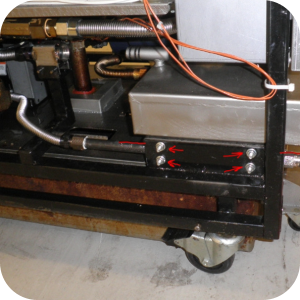
Drill 4 5/16 in. diameter or equivalent holes, about 1 in. from the front and back of the frame area. Drilling the holes will allow two U-bolts to hold the pipe.
-
Position the pipe and holes as high up against frame as possible.
-
Clean up metal shavings and ensure sharp edges are deburred.
-
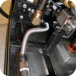
Install 12 in. flex tube only fitting on pipe / QD assembly and position assembly into fryer.
-
Slowly bend the flex tube to mate up with elbow fitting on selector valve. Ensure no kinking of the tube.
-
Install U-bolts around 3/8 in. pipe.
-
Insert U-bolts through frame and loosely fasten with nuts.
-
Position pipe as high as possible with Q.D. fitting just outside of frame.
-
Install ATO tank and final flex tube, ensuring it is not touching the ATO tank.
-
Position flex tube in between ATO tank and cross frame member.
-
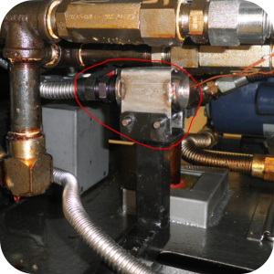
Adjust and tighten elbow fitting on selector valve.
-
Tighten nuts on U-bolts and ensure all plumbing connections are tight.
-
Control software program version 1.55 or later is needed to be able to use the front dispose feature. The latest SW is available on the Henny Penny website.
-
Open tech mode through main menu and select that front dispose hardware is now installed.
-
Main menu.
-
PRG.
-
TECH MODE.
-
Enter code 11221122.
-
Scroll through settings to step T-4A.
-
Select Yes front dispose installed.
-
-
At this point the fryer will still dispose in the same setting, either none or rear. To use front dispose as default change to "Front Hose" in special programs.
-
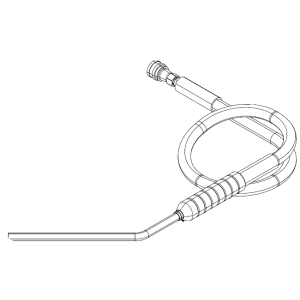
Test to ensure no leaks. Recommended to use filter hose assembly to connect to front dispose to test and for future disposal into a portable container.
-
Install left side panel, condensate tank and put fryer back into service.
Related Content
Replacing the Filter Pump Motor
Replacing the Filter Pump Motor Seal
Replacing the Filter Pump Motor Rollers
Replacing the Selector Valve Motor and Encoder
Replacing the Drain Valve and Actuator
Replacing the Nylatron Vertical Strip
Velocity Nylatron Vertical Filler Strips Installation Instructions
Selector Valve Motor/Encoder Replacement
Velocity Deadweight Orifice Clean-out Tool Installation and Maintenance
Velocity Lid Cable Replacement
Instructions to replace PXE Interlock Latch Pivot Pin
Remove Selector Valve to ATO flex tube
Flexible Line Replacement Kit (Formed Tube), (Standard, Bulk-Oil Fryer)
Flexible Line Replacement Kit (Formed Tube), (Standard, NON Bulk-Oil Fryer)
Troubleshooting Slow Refill No Detect Error on OXE 100
Troubleshooting Bulk Tank Full Message on OXE 100
OXE 100 Troubleshooting the E-18 Level Probe Failure Error Code
OXE 100 Troubleshooting the Oil Not Pumping
Lid Latch Adjustment or Replacement
Armored Cable Grounding Installation Instructions for Australia
ZigBee Radio Communication Kit
Temp/Level Probe Fitting Replacement
Label Replacement Instructions
High Limit Protection Probe Installation (CE Version built prior to 5/2020, ALL Versions after)
High Limit Protection Probe Installation (UL Version built prior to 5/2020)
Menu Card Removal Replacement Instructions
Save and Load Setpoint Instructions
Velocity High Limit Adjustment Instructions
Replacing the Filter Pump Motor
Replacing the Filter Pump Motor Seal
Replacing the Filter Pump Motor Rollers
Replacing the Drain Valve and Actuator
Replacing the Selector Valve Motor and Encoder
Troubleshooting a PXE 100 E-93 Error Code
Troubleshooting Slow Refill No Detect Error on PXE 100
Troubleshooting Bulk Tank Full Message on PXE 100
PXE 100 Troubleshooting the E-18 Level Probe Failure Error Code
PXE 100 Troubleshooting the Oil not Pumping
Velocity Steam Box Swap-out Instructions
Lid Handle Replacement Instructions
Add pressure gauge to PXE unit Instructions (Japan / Hong Kong)
Add pressure gauge to PXE unit Instructions
Reference
Product Racking Recommendations
OXE 100 KFC Annual Inspection Certification
Product Racking Recommendations