Velocity Lid Cable Replacement
1/2 in. Wrench
3/8 in. Nut Driver
Adjustable wrench
Crosstip head screwdriver
Loctite
Pipe thread sealant
Kit number
140610
Estimated Time
60 Minutes
Purpose
The weight carriage on the rear of the fryer counter-balances the lid system for easier operation. Two cables attached to it; the safety cable on the left-side and the lifting cable in the middle. The lifting cable tension should be tight and the safety cable tension should be loose enough that when squeezing the cable together, the two sides can touch. Both cables should be replaced in pairs. The white label denotes the cable replacement date and should be affixed to the back of the fryer's frame.
-
Locate a 3/8 in. nut driver.
-
Use a 3/8 in. nut driver to remove the nuts securing rear shroud of the fryer and remove the shroud.
-
Use a crosstip head screwdriver to remove screws securing the top cap and remove.
-
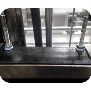
Lower the lid until it latches, and then insert two 5/16 in. carriage bolts. One bolt through each side of the weight carriage and in to the frame to secure the carriage. Ensure the carriage is level.
-
Carriage bolt holes are provided in the frame for securing the carriage.
-
Unscrew and remove both cables from the weight carriage assembly and then the chassis.

-
Remove weights as needed.
-
Screw a 5/16 in. lock-nut on each end of the new cables.
-
Apply blue loctite thread sealant to the cable threads.
-
Use an adjustable wrench to screw one end of each new cable in to the weight carriage assembly until tight.
-
Use a 1/2 in. wrench to tighten the lock-nut against the weight carriage assembly, this will secure both cables in place.
-
Thread the cables over the pulleys and down behind the weight assembly.
-
Apply blue loctite thread sealant to the cable threads.
-
Insert both cables into the holes in the chassis.
-
Screw a 5/16 in. nut on to the end of each of the cables and then tighten.
-
The lifting cable tension should be tight and the safety cable tension should be loose enough that when squeezing the cable together, the two sides can touch.
-
Tighten the lock-nut against the top of the bracket, securing the cable.
-
Remove the two carriage bolts securing the weight carriage against the fryer's frame. Retain the bolts for future use.
-
Raise the lid up and down to ensure free movement of the weight carriage and that it is level. Correct as needed.
-
Replace the top cap and rear shroud the repair is now complete.
Label Fryer to Denote Cable Replacement
-
After replacing both cables locate the white label and using a marker or pen write the cable replacement month and year on the white label.
-
Place the label on the back of the fryer.
-
Place the clear label protector overtop of the white label to prevent ink from wiping away during future cleanings.
Related Content
Replacing the Filter Pump Motor
Replacing the Filter Pump Motor Seal
Replacing the Filter Pump Motor Rollers
Replacing the Selector Valve Motor and Encoder
Replacing the Drain Valve and Actuator
Replacing the Nylatron Vertical Strip
Velocity Nylatron Vertical Filler Strips Installation Instructions
Selector Valve Motor/Encoder Replacement
Velocity Deadweight Orifice Clean-out Tool Installation and Maintenance
Instructions to replace PXE Interlock Latch Pivot Pin
Front Dispose Addition (for Bulk Oil Units)
Remove Selector Valve to ATO flex tube
Flexible Line Replacement Kit (Formed Tube), (Standard, Bulk-Oil Fryer)
Flexible Line Replacement Kit (Formed Tube), (Standard, NON Bulk-Oil Fryer)
Troubleshooting Slow Refill No Detect Error on OXE 100
Troubleshooting Bulk Tank Full Message on OXE 100
OXE 100 Troubleshooting the E-18 Level Probe Failure Error Code
OXE 100 Troubleshooting the Oil Not Pumping
Lid Latch Adjustment or Replacement
Armored Cable Grounding Installation Instructions for Australia
ZigBee Radio Communication Kit
Temp/Level Probe Fitting Replacement
Label Replacement Instructions
High Limit Protection Probe Installation (CE Version built prior to 5/2020, ALL Versions after)
High Limit Protection Probe Installation (UL Version built prior to 5/2020)
Menu Card Removal Replacement Instructions
Save and Load Setpoint Instructions
Velocity High Limit Adjustment Instructions
Replacing the Nylatron Vertical Strip
Converting Velocity Pressure Fryer to Open Fryer
Velocity Steam Box Swap-out Instructions
Lid Handle Replacement Instructions
Add pressure gauge to PXE unit Instructions (Japan / Hong Kong)
Add pressure gauge to PXE unit Instructions
Troubleshooting a PXE 100 E-84 Error Code
Troubleshooting a PXE 100 E-13 Error Code
Reference
Product Racking Recommendations
OXE 100 KFC Annual Inspection Certification
Product Racking Recommendations