Velocity Steam Box Swap-out Instructions
5/8 in. Wrench,
Crosstip head screwdriver,
Electric drill with crosstip head bit.
Flathead Screwdriver
Kit number
140698
Estimated Time
1 Hour
-
Remove the deadweight assembly by doing the following:
-
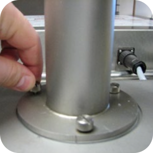
Loosen the three thumb screws near the steam exhaust and pull up on the steam outlet.
-
Clean the deadweight and steam exhaust pipe in hot soapy water and set aside.
-
Remove the circular steam exhaust gasket.
-
Clean surface of fryer top cap as needed.
-
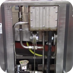
Remove the service access panel.
-
Use a crosstip head screwdriver to remove 4 vat head screws from the top access panel.
-
Remove the service access panel and set aside.
-
Remove the steam box manifold by first loosening the four compression nuts holding the steam box manifold tube in place.
-
Remove and set the old manifold tube aside for cleaning. Do not clean now.
-
Remove the solenoid valve by first removing the solenoid valve coil and set aside.
-
Loosen the compression fitting to remove the valve from steam box tubing.
-
Use the solenoid valve rebuild kit to rebuild.
-
Set aside for re-installation.
-
Remove safety relief valve by loosing the compression fitting to remove from tubing.
-
Clean the safety relief valve and tubing in hot soapy water and set aside.
-
Inspect the safety relief valve and ensure proper operation. Replace the safety relief valve if damaged or inoperable.
-
Clean out tubing by removing the clean out plug and clean the tubing from vat outlet all the way through to ensure the port is clean.
-
Install the clean out plug.
-
Remove the condensation hose by using a flathead screwdriver to loosen the upper hose clamp on the condensation pipe.
-
Remove the upper part of the condensation drain hose from the steam box pipe.
-
Using a cross-tip screwdriver or drill with a bit, remove the right-side panel to access the lower end of the condensation hose.
-
Using a straight tip screwdriver, loosen the lower hose clamps on the condensation pipe.
-
Remove the lower part of the condensation drain hose from the lower condensation pipe.
-
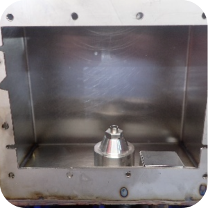
Using a cross tip screwdriver, remove panhead screws, and then remove the steam box cover. Older models have 10 screws but the newer models have 12 screws.
-
Remove steam box and baffle assembly, if they have 10 screw holes it is an obsolete design and should be discard.
-
If cover and baffle assembly have 12 screw holes, clean in hot soapy water and set aside.
-
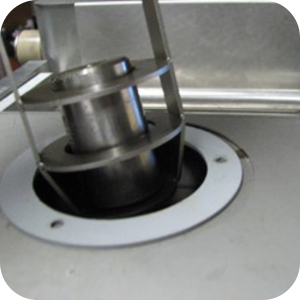
Remove and clean the deadweight orifice using a 5/8 in. wrench to remove the orifice.
-
Clean the orifice in hot soapy water, and then use the orifice cleaning tool attached to the back of the fryer.
-
Inspect the deadweight orifice by looking carefully for any nicks or damage of the orifice edge.
-
Set aside the orifice for reuse later.
-
If the orifice is damaged replace it with a new orifice.
-
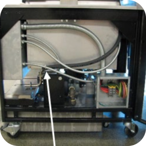
Remove the steam box from the fryer by using a nut driver to remove four nuts, two on the bottom and two in teh back of the steam box.
-
Remove and set the old manifold tube aside for cleaning later. Do not clean now.
-
Install the steam box into the fyer by first aligning the steam box in the fryer brackets.
-
Use a nut driver install four nuts, two on the bottom and two in the back of the steam box.
-
Use a 5/8 in. wrench to install the old, cleaned orifice into the new steam box.
-
Install the baffle, steam box cover assembly, and gasket tightening 12 panhead screws to snug in a crosswise pattern to apply equal pressure to the gasket.
-
Install the condensation hose by placing one of the old hose clamps over one end of the new condensation hose.
-
Push the same end of the condensation hose onto the upper steam box condensation tube.
-
Using a straight tip screwdriver, tighten to snug the hose clamp on the upper condensation pipe.
-
Place the other old hose clamp over the opposite end of the new condensation hose.
-
Push the end of the condensation hose onto the lower steam box condensation tube.
-
Use a flathead screwdriver to tighten the hose clamp on the lower condensation pipe.
-
Install the safety relief valve to the compression tubing by snugging the compression fitting. Replace the safety relief valve if damaged or inoperable.
-
Install the rebuilt solenoid valve by installing the solenoid vlave to the compression tubing by snugging the compression fitting.
-
Install the solenoid valve coil. Refer to the instructions in the kit.
-
Install the new compression fitting from the steam box kit by snugging to the bottom of the steam box.
-
Install the new steam box manifold to the steam box by snugging four compression nuts.
-
Use a crosstip head screwdriver or electric drill with bit to install 4 vat head screws securing the service access panel.
-
Inspect the steam exhaust hose insert that is glued into the steam exhaust at the top of the fryer. If this insert is missing, collapsing or damaged, replace the insert by cutting out the old insert and installing a new insert using a silicone rated for application of 220F or higher.
-
Replace the circular steam exhaust gasket, and then install the deadweight, deadweight carrier and steam exhaust assembly. It does not matter which side of the deadweight faces down.
-
Secure the steam exhaust assembly using the thumb screws provided in the steam box swap-out kit.
Clean and Reuse Oil Laden Parts
The oil laden parts from the fryer may be cleaned and reused on another Velocity PXE 100 fryer assuming the parts are not damaged. Use warm soapy water, scrub brushes and a scraper to clean each part, and then dry and re-package for reuse. Non-reusable parts must be ordered to make the kit whole for the next service call. Order the following parts.
Related Content
Replacing the Nylatron Vertical Strip
Converting Velocity Pressure Fryer to Open Fryer
Armored Cable Grounding Installation Instructions for Australia
Lid Latch Adjustment or Replacement
Velocity Nylatron Vertical Filler Strips Installation Instructions
Lid Handle Replacement Instructions
Velocity Deadweight Orifice Clean-out Tool Installation and Maintenance
Velocity Lid Cable Replacement
Add pressure gauge to PXE unit Instructions (Japan / Hong Kong)
Instructions to replace PXE Interlock Latch Pivot Pin
Add pressure gauge to PXE unit Instructions
Troubleshooting a PXE 100 E-84 Error Code
Troubleshooting a PXE 100 E-13 Error Code
ZigBee Radio Communication Kit
Selector Valve Motor/Encoder Replacement
Front Dispose Addition (for Bulk Oil Units)
Remove Selector Valve to ATO flex tube
Temp/Level Probe Fitting Replacement
Label Replacement Instructions
High Limit Protection Probe Installation (CE Version built prior to 5/2020, ALL Versions after)
High Limit Protection Probe Installation (UL Version built prior to 5/2020)
Menu Card Removal Replacement Instructions
Save and Load Setpoint Instructions
Flexible Line Replacement Kit (Formed Tube), (Standard, Bulk-Oil Fryer)
Flexible Line Replacement Kit (Formed Tube), (Standard, NON Bulk-Oil Fryer)
Velocity High Limit Adjustment Instructions
Reference
Product Racking Recommendations
PXE 100 Inspection and Planned Maintenance