Flexible Line Replacement Kit (Formed Tube), (Standard, NON Bulk-Oil Fryer)
3/4 in. Wrench,
Hammer,
Hacksaw or Saw,
Pliers
Kit number
140444
Estimated Time
30 Minutes to 1 Hour
-
Remove Filter Pan, Oil Top-off Tank and Condensate Tank (If PXE) from fryer.
-
Pull fryer out until the side panels can be removed; then remove both side panels.

-
Remove the two P-clips and mounting hardware.
-
Use a 3/4 in. wrench to loosen the 3/4 in. flexible line from both end fittings and remove.
-
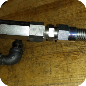
Remove the fitting attached to the elbow coming out of the pump and discard.
-
Add one of FP01-170 to replace the fitting removed. This will allow the hard tube to connect to the pump. Ensure to add a food grade, stainless steel compatible pipe sealant to the threads.
-
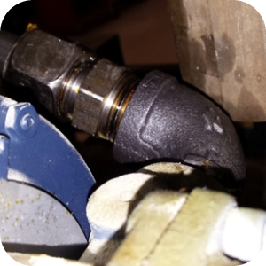
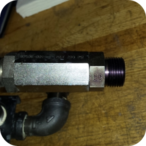
Remove the two fittings and discard.
-
Install one FP01-280 into the check valve in place of the two fittings removed. No pipe sealant to be used.
-
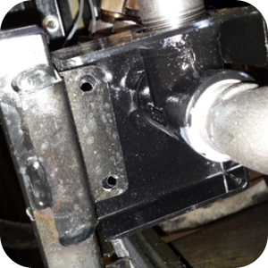
Remove the two nuts holding the oil manifold bracket in place on the fryer. Depending on fits and tolerances of the assembled parts, it will be necessary to either remove the two clinch studs from that same bracket or remove the entire bracket and vertical square tube from the fryer.
-
Using pliers or a hammer and punch can aid with the removal of the clinch studs; a reciprocating saw or hack saw will be necessary to remove the tube / bracket. Touch up paint is recommended to prevent corrosion on the exposed frame.
-
Option 1: Remove the vertical square tube and bracket from the fryer. They are no longer needed and could get in the way.
-
Option 2: Remove the two clinch studs from this bracket found on the fryer. They are no longer needed, and could get in the way.
-
-
The oil manifold should now be "loose" in the fryer, held in place only by the 1/2 in. flexible lines going from the manifold to the pot, and to the top-off pump.
-
If necessary, install 3/8 NPT cap to formed assembly tube, use a food grade stainless steel compatible pipe sealant on the threads. Some fryers may have a pressure transducer attached to this tube, however this is not included in this kit.
-
Loosely attach the assembly with the downward bend towards the pump and the small tube protruding to the side towards the left side of the fryer and hand tighten.
-
The oil manifold can be adjusted in space slightly to allow easier fitup of the hard tube.
-
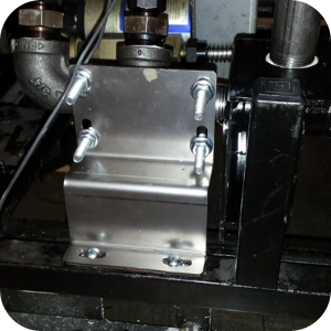
Place U-bolts on both sides of the piping tree and tighten the manifold mounting bracket.
-
Attach to the frame using two self-drilling screws.
-
Install oil manifold mounting bracket.
-
Use two self-drilling screws to attach the oil manifold mounting bracket to the fryer frame. The exact placement of the bracket on the frame is NOT critical and is designed to be flexbile based on tolerances encountered in tightening fittings, slight differences in the bending of the hard tube, etc.
-
Ensure clearance of the 1/2 in. flexbile tubes, fittings and the formed tube to position the oil manifold bracket.
-
Securely tighten fittings on both ends of the formed tube assembly.
-
Ensure all fittings are tight.
-
Re-install the fryer side panels.
-
Unit is now ready for operation.
Related Content
Replacing the Filter Pump Motor
Replacing the Filter Pump Motor Seal
Replacing the Filter Pump Motor Rollers
Replacing the Selector Valve Motor and Encoder
Replacing the Drain Valve and Actuator
Replacing the Nylatron Vertical Strip
Velocity Nylatron Vertical Filler Strips Installation Instructions
Selector Valve Motor/Encoder Replacement
Velocity Deadweight Orifice Clean-out Tool Installation and Maintenance
Velocity Lid Cable Replacement
Instructions to replace PXE Interlock Latch Pivot Pin
Front Dispose Addition (for Bulk Oil Units)
Remove Selector Valve to ATO flex tube
Flexible Line Replacement Kit (Formed Tube), (Standard, Bulk-Oil Fryer)
Troubleshooting Slow Refill No Detect Error on OXE 100
Troubleshooting Bulk Tank Full Message on OXE 100
OXE 100 Troubleshooting the E-18 Level Probe Failure Error Code
OXE 100 Troubleshooting the Oil Not Pumping
Lid Latch Adjustment or Replacement
Armored Cable Grounding Installation Instructions for Australia
ZigBee Radio Communication Kit
Temp/Level Probe Fitting Replacement
Label Replacement Instructions
High Limit Protection Probe Installation (CE Version built prior to 5/2020, ALL Versions after)
High Limit Protection Probe Installation (UL Version built prior to 5/2020)
Menu Card Removal Replacement Instructions
Save and Load Setpoint Instructions
Velocity High Limit Adjustment Instructions
Replacing the Filter Pump Motor
Replacing the Filter Pump Motor Seal
Replacing the Filter Pump Motor Rollers
Replacing the Drain Valve and Actuator
Replacing the Selector Valve Motor and Encoder
Troubleshooting a PXE 100 E-93 Error Code
Troubleshooting Slow Refill No Detect Error on PXE 100
Troubleshooting Bulk Tank Full Message on PXE 100
PXE 100 Troubleshooting the E-18 Level Probe Failure Error Code
PXE 100 Troubleshooting the Oil not Pumping
Velocity Steam Box Swap-out Instructions
Lid Handle Replacement Instructions
Add pressure gauge to PXE unit Instructions (Japan / Hong Kong)
Add pressure gauge to PXE unit Instructions
Reference
Product Racking Recommendations
OXE 100 KFC Annual Inspection Certification
Product Racking Recommendations