Applies to:
![]()
ALL CUSTOMERS
PFG 690 Stabilizer Retrofit Instructions
1/4 in. Drill bit
Blue loctite
Crosstip head screwdriver
Electric drill
Kit number
14231
Estimated Time
1 Hour
-
Remove back shroud.
-
Disconnect gray plastic trim strip at top weight.
-
Disconnect steam box and remove.
-
Disconnect blower bracket and allow the blower to lay down by the weights. (Flue must be out of the way.)
-
Break plumbing and electrical connections going through left and right shrouds, then remove shrouds.
-
Replace old black rubber bumper with new.
-
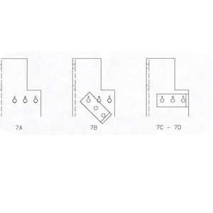
Install two angle brackets to the outside of the u-channel using the following procedure on each side: Note: Black angle must remain in the same position throughout this process.
-
Remove screws a & b (see illustration 2).
-
Install new bracket using new bolt in position a only as shown.
-
Use blue loctite.
-
After securing bolt in hole a, then remove screw c.
-
Pivot bracket up into position and install new screws in positions. Use blue loctite.
-
Repeat on the other side.
-
-
Drill four new holes using ¼” drill bit (#MS01-426). See illustration 3 for locations. Note: White wheels must be shielded from all metal shavings!
-
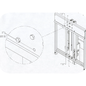
Install two rails using ¼” hardware (short ¼-20 hex bolts with keps nut on bottom angle, long ¼-20 hex bolt with spacer and keps nut on top plate). While installing rails slide the plastic pads into position.
-
Re-install left and right shrouds, blowers, and flue only.
-
Before re-installing the remainder it may be necessary to adjust the rails with the shims provided.
-
To test, the lid must be in the up position. While standing in from of the fryer, grasp the center of the lid handle with one hand. Attempting to move the lid back and forth should cause the entire fryer to shake. There should be no looseness or rattling in the slide guides. If any of the above is the case, shim rail. Usually any looseness in the plastic pads – even if it appears to be all on one side, will require equal shimming on both sides and top and bottom.
-
Once all looseness is removed grease backside of rail with spindle lube.
-
Re-install remaining parts.
Related Content
Label Application and Location for the 8 Head Fryer
Rear Cover Removal Instructions
Installing Optional Crumb Basket
I-Beam Cable Hole Plug Installation
FM08-502 8 Head Replacing KFC Control
FM08-481 8 Head Replacing the Control
PFG-69X & OFG-39X Gas Valve Replacement Kit
Repositioning/Rewiring Air Valves for 220240V Model 690/390 fryers
Repositioning / Rewiring Air Valves for 120V Model 690/390 fryers
FM07-558 Gas Valve Replacement Kit
PFG-690/691 & OFG-390/391 Pump Motor Relay Kit
Conversion From C8000 Control to KFC SMS Control
Manifold Retrofit Kit Instructions
Replace Nylatron Slides on PFG 690 and 691
PFG 690 and 691 Installing Filter Rinse Hose
PFG 690/691 Ignition Module Kit
Mounting the OFG 390 and PFG 690 Vacuum Switch
Conversion From Standard 690 Control to S/M Control
PFG 690 and 691 Temperature Probe CE Instructions
Replace Gas Valve Assembly with Gas Valve and Solenoid Assembly
Replacing Gas Valve Assembly With Gas Valve and Solenoid Assembly
Air Switch Monitoring Retrofit Kit Instructions
PFG 691 C8000 Retrofit Instructions
PFG 690 and 691 Lid Cable Replacement
Operating Instructions for PFG-691/OFG-391 Direct-Connect Oil System
Direct-Connect Retrofit Instructions (For use on fryers after SN: 391-LH016JC & 691-LH029JC)
CE Gas Valve Adjustment Instructions
Replacing High Limit Thermocouple
PFG 691 Attaching the Rinse Hose Instructions
Reference
PFG 690 and 692 Inspection and Planned Maintenance
PFG 690 and 692 KFC Annual Inspection Certification