Applies to:
![]()
ALL CUSTOMERS
PFG 690 to 692 Retrofit Kit
3/8 in. Socket
3/16 in. drill bit
Crosstip head screwdriver
Electric drill
Thread sealant
Wire cutters
Wire strippers
Kit number
140122
140388
140395
14788
Estimated Time
1 Hour

|
To avoid electrical shock or property damage, move the power switch to OFF and disconnect power. |
Remove the FAST controls from the control area.
Label and disconnect the wires to the power switch.
Remove the screws securing the front panel assembly and remove from unit.
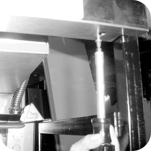
Ensure oil is drained from vat, then using an 11/16” crowsfoot, or socket, remove the FAST probe from the vat. Install the 3/8” to 1/8” reducer in the probe’s place, using pipe thread sealant.
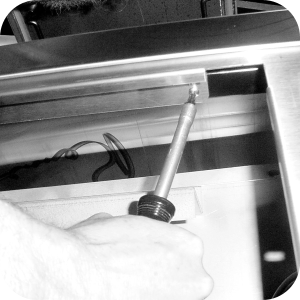
Install the compression fitting in the reducer, using pipe thread sealant.
Slide the ferrule and nut, from the compression fitting, over the new probe, and insert the probe into the compression fitting.
Locate temperature probe through vat wall.
Place gauge against vat wall.
Push temperature probe through until it makes contact with gauge.
Tighten temperature probe in place.
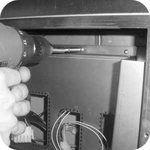
Use 3 sheet-metal screws in the kit to fasten the inner shroud to the upper frame rail inside the control area.
Route 15 pin harness and probe harness through cutouts on the inner shroud.

Locate the new front panel assembly. Connect the wires to the power switch and install the front panel to the unit, using the screws removed previously.
Connect 15-pin connector and probe connector to the back of the new Henny Penny control.
Secure the new Henny Penny controls in place with 2 screws provided in the kit.
Restore electrical power to the unit and unit is now ready for use.
Related Content
Label Application and Location for the 8 Head Fryer
Rear Cover Removal Instructions
Installing Optional Crumb Basket
PFG 690 Stabilizer Retrofit Instructions
I-Beam Cable Hole Plug Installation
FM08-502 8 Head Replacing KFC Control
FM08-481 8 Head Replacing the Control
PFG-69X & OFG-39X Gas Valve Replacement Kit
Repositioning/Rewiring Air Valves for 220240V Model 690/390 fryers
Repositioning / Rewiring Air Valves for 120V Model 690/390 fryers
FM07-558 Gas Valve Replacement Kit
PFG-690/691 & OFG-390/391 Pump Motor Relay Kit
Conversion From C8000 Control to KFC SMS Control
Manifold Retrofit Kit Instructions
Replace Nylatron Slides on PFG 690 and 691
PFG 690 and 691 Installing Filter Rinse Hose
PFG 690/691 Ignition Module Kit
Mounting the OFG 390 and PFG 690 Vacuum Switch
Conversion From Standard 690 Control to S/M Control
PFG 690 and 691 Temperature Probe CE Instructions
Replace Gas Valve Assembly with Gas Valve and Solenoid Assembly
Replacing Gas Valve Assembly With Gas Valve and Solenoid Assembly
Air Switch Monitoring Retrofit Kit Instructions
PFG 691 C8000 Retrofit Instructions
PFG 690 and 691 Lid Cable Replacement
Operating Instructions for PFG-691/OFG-391 Direct-Connect Oil System
Direct-Connect Retrofit Instructions (For use on fryers after SN: 391-LH016JC & 691-LH029JC)
CE Gas Valve Adjustment Instructions
Replacing High Limit Thermocouple
Reference
PFG 690 and 692 Inspection and Planned Maintenance