Applies to:
![]()
ALL CUSTOMERS
Conversion From Standard 690 Control to S/M Control
1/4 in. Drill bit
Blue loctite
Crosstip head screwdriver
Electric drill
Kit number
14254
Estimated Time
30 Minutes
-
Disconnect the fryer from the power supply.
-
Loosen 2 screws and drop control down to horizontal service position.
-
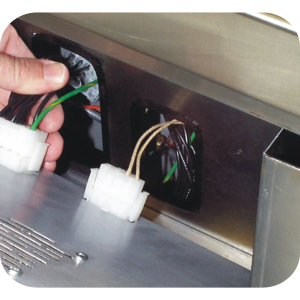
Disconnect electrical connections to controller.
-
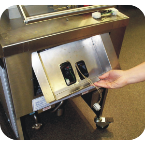
Carefully place the new shroud into the control area. Pull the wire harness and probe connection through as shown.
-
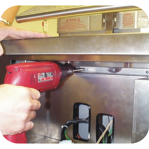
Hold the shroud so that the flange with the 3 round holes is even with the top of the insulation panel. The shroud should be centered in the control panel opening. Be certain that the high limit capillary bulb goes through the cut out at the top left and is not “pinched” behind the new sheet metal. While holding this cover in place, install 3 self-drilling screws until tight, or mark then predrill pilot holes.
-
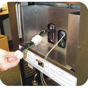
Add the new extension to the 15-pin connector.
-
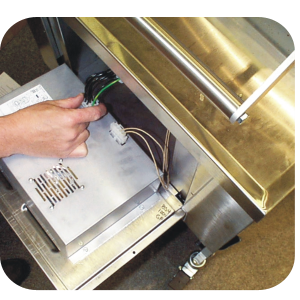
Place new control on the fryer in the horizontal position.
-
Connect electrical connection.
-
Rotate control up into its normal position. Be careful as you raise the control that the large 15-pin connector goes through the large hole in the shroud (Figure 5).
-
Secure the control to the fryer.
Related Content
FM08-502 8 Head Replacing KFC Control
FM08-481 8 Head Replacing the Control
Conversion From C8000 Control to KFC SMS Control
PFG 691 C8000 Retrofit Instructions
Troubleshooting the SMS Control Online Projection System (OPS) Connection
Troubleshooting the C8000 Open Fryer Message
Troubleshooting the PFG 690 and 692 E-41 Control Programming Lost Error Code
I-Beam Cable Hole Plug Installation
Label Application and Location for the 8 Head Fryer
PFG-69X & OFG-39X Gas Valve Replacement Kit
Repositioning/Rewiring Air Valves for 220240V Model 690/390 fryers
Repositioning / Rewiring Air Valves for 120V Model 690/390 fryers
FM07-558 Gas Valve Replacement Kit
PFG-690/691 & OFG-390/391 Pump Motor Relay Kit
Rear Cover Removal Instructions
Manifold Retrofit Kit Instructions
Replace Nylatron Slides on PFG 690 and 691
Installing Optional Crumb Basket
PFG 690 and 691 Installing Filter Rinse Hose
PFG 690 Stabilizer Retrofit Instructions
PFG 690/691 Ignition Module Kit
Mounting the OFG 390 and PFG 690 Vacuum Switch
PFG 690 and 691 Temperature Probe CE Instructions
Replace Gas Valve Assembly with Gas Valve and Solenoid Assembly
Replacing Gas Valve Assembly With Gas Valve and Solenoid Assembly
Air Switch Monitoring Retrofit Kit Instructions
PFG 690 and 691 Lid Cable Replacement
Operating Instructions for PFG-691/OFG-391 Direct-Connect Oil System
Direct-Connect Retrofit Instructions (For use on fryers after SN: 391-LH016JC & 691-LH029JC)
CE Gas Valve Adjustment Instructions
Replacing High Limit Thermocouple
Reference
PFG 690 and 692 Inspection and Planned Maintenance