Retrofitting High Limit Upgrade Kit
 Required tools
-
Wrench or Crows Foot: 11/16 in. (18 mm), 1/2 in. (13 mm)
-
Socket or Nut Driver: 5/16 in. (8 mm), 3/8 in. (10 mm)
-
Drill with Crosstip Bit
-
Crosstip Head Screwdriver
-
Adjustable Wrench
-
Hole Punch or Step Bit: 5/8 in. (16 mm)
-
Needle Nose Pliers
Kit contents
-
High Limit TC Probe
-
High Limit Module and Mounting Bracket
-
Reset Switch and Mounting Enclosure
-
Updated Wiring Diagram
-
Wiring
-
Miscellaneous Components (Screws, Terminals, Connectors, etc.)
Kit number
140849
Estimated Time
2 hour

|
Only perform this procedure when the unit is cool or severe burns may result. |
Preparing Fryer
-
Turn power switch off.
-
Remove oil from the fryer.
-
Verify drain pan is underneath fryer and empty.
-
Using PPE, slowly open the drain valve and allow the vat to empty completely.
-
Ensure fryer is cool to touch before moving.
-
Pull out the fryer and unplug from power source.
Removing Old High Limit Bulb and Cap Probe
-
Lower front display panel, disconnect wiring, and set aside if in the way.
-
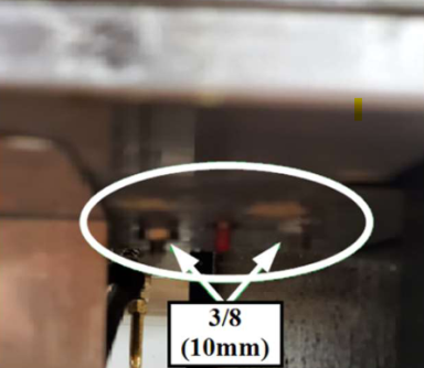
Using a 3/8 in. (10 mm) socket or wrench, locate and remove the bulb and cap high limit mounting nuts under fryer.
-
Disconnect wiring from high limit.
-
If lid is down, unlatch lid, raise it up, and remove carriage from fryer.
-
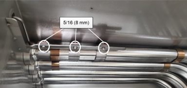
Using a 5/16 in (8 mm) socket or hex driver, remove the three screws from the high limit thermocouple bracket in the vat.
-
Remove left side panel.
-
Remove vat extension and probe from bat and discard.
Installing High Limit Thermocouple
-
Clean the high limit brackets and threads of the fitting in the vat.
-
Apply white thread sealant to new high limit bushing, angle probe, and insert into vat.
-
Thread bushing into vat and tighten using a 11/16 in. (18 mm) wrench or crows foot.
-
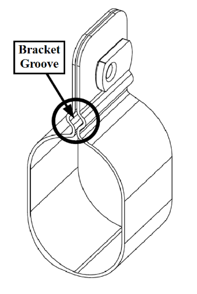
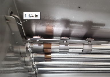
Install the high limit probe into three mounting brackets and spacer on the burner tube making sure the probe goes into the grooves of the brackets and snug screws using a 5/16 in. (8 mm) socket or hex driver, but do not fully tighten.
-
Space the probe from the vat wall 1 1/4 in., verify the probe does not extend beyond the spacer bracket and tighten screws.
-
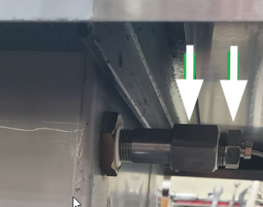
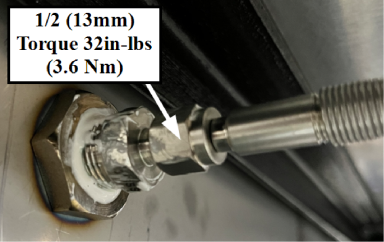
Using a 1/2 in. (13 mm) torque wrench, torque the high limit compression fitting to 32 in-lbs (3.6 Nm).

|
Do not over tighten compression nut. This can damage the probe. |
Installing Reset Switch and Module
IMPORTANT: Remove the drain pan from the fryer before proceeding to next step.
-
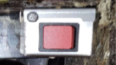
Using a hole (knock-out) punch, open the limit reset hole on the shroud to 5/8 in. Insert grommet provided in kit into the opening.
NOTE: The right-side panel may need to be removed to access the location of the original high limit hole.
-
Punch out one side of the reset switch box according to best fit up and reset access for store.
-
Using the diagram provided in the kit, wire up the new high limit reset switch and run wires through the switch box.
-
Seat the switch into the box and run the wires through the cover.
-
Screw in the cover switch box and mount the box using the 3/8 in. (10 mm) nuts.
-
-
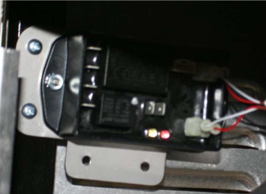
Using a 5/16 in. (8 mm) wrench, attach module to bracket as shown.
-
Wire module per wiring diagram. High limit wires should be on the right side.
-
Mount in the module using the two self-tap screws provided onto the left inner frame rail as shown above.
-
Finalize the complete wiring into the power wires if not completed yet per the new wiring diagram.
-
Working in reverse order, complete steps 1, in the Removing Old High Limit Bulb and Cap Probe section, through step 1, in Preparing Fryer section, and return fryer to operation.
NOTE: It is recommended to wire up the module per the new wiring diagram prior to installing it in the fryer.
Related Content
Replacing the High Temperature Limit Control
Replacing the Temperature Probe
Replacing the Gas Control Valve
Replacing the Flame Sensor Assembly
Replacing the Ignition Modules
Replacing the Ignitor Assembly
Replacing High Limit Thermocouple
Replacing the High Temperature Limit Control
Replacing the Temperature Probe
Replacing the Gas Control Valve
Replacing the Flame Sensor Assembly
Replacing the Ignitor Assembly
Replacing the Ignition Modules
PFG-69X & OFG-39X Gas Valve Replacement Kit
Repositioning/Rewiring Air Valves for 220240V Model 690/390 fryers
Repositioning / Rewiring Air Valves for 120V Model 690/390 fryers
FM07-558 Gas Valve Replacement Kit
Manifold Retrofit Kit Instructions
PFG 690/691 Ignition Module Kit
Mounting the OFG 390 and PFG 690 Vacuum Switch
PFG 690 and 691 Temperature Probe CE Instructions
Replace Gas Valve Assembly with Gas Valve and Solenoid Assembly
Replacing Gas Valve Assembly With Gas Valve and Solenoid Assembly
Air Switch Monitoring Retrofit Kit Instructions
CE Gas Valve Adjustment Instructions
Troubleshooting the PFG 690 and 692 E-4 Control Overheating Error Code
Troubleshooting the PFG 690 and 692 E-5 Oil Overheating Error Code
Troubleshooting the PFG 690 and 692 E-6 Temperature Probe Error Code
Troubleshooting the PFG 690 and 692 E-10 High Limit Error Code
I-Beam Cable Hole Plug Installation
FM08-502 8 Head Replacing KFC Control
FM08-481 8 Head Replacing the Control
Label Application and Location for the 8 Head Fryer
PFG-690/691 & OFG-390/391 Pump Motor Relay Kit
Conversion From C8000 Control to KFC SMS Control
Rear Cover Removal Instructions
Replace Nylatron Slides on PFG 690 and 691
Installing Optional Crumb Basket
PFG 690 and 691 Installing Filter Rinse Hose
PFG 690 Stabilizer Retrofit Instructions
Conversion From Standard 690 Control to S/M Control
PFG 691 C8000 Retrofit Instructions
PFG 690 and 691 Lid Cable Replacement
Operating Instructions for PFG-691/OFG-391 Direct-Connect Oil System
Direct-Connect Retrofit Instructions (For use on fryers after SN: 391-LH016JC & 691-LH029JC)
Reference
Replacing High Limit Thermocouple